Electrical Symbols, Electrical Diagram Symbols

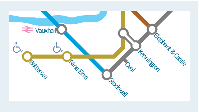
This spatial infographic example was created on the base of the tube map from the Transport for London website.
[tfl.gov.uk/ assets/ images/ general/ 24746-nle-gallery-tube-map.jpg]
"The Tube map is a schematic transit map of the lines and stations of London's public rapid transit railway systems, namely the London Underground (commonly known as the Tube, hence the name), Docklands Light Railway, London Overground and Emirates Air Line, as well as being incorporated into Greater London connections maps.
As a schematic diagram, it shows not necessarily the geographic but rather the relative positions of stations along the lines, stations' connective relations with each other and fare zones. The basic design concepts have been widely adopted for other network maps around the world, especially that of mapping topologically rather than geographically." [Tube map. Wikipedia]
The spatial infographics example "Metro map - Northern line extension to Battersea via Nine Elms" was created using the ConceptDraw PRO diagramming and vector drawing software extended with the Spatial Infographics solution from the area "What is Infographics" of ConceptDraw Solution Park.
Tube map
Flow chart Example. Warehouse Flowchart


Flowchart Software


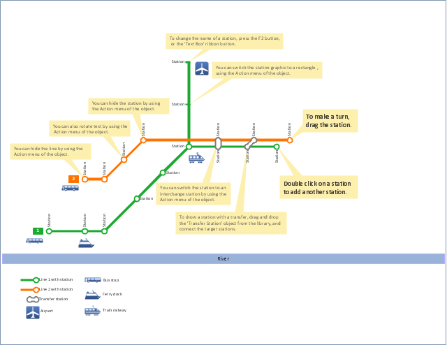
"A transit map is a topological map in the form of a schematic diagram used to illustrate the routes and stations within a public transport system - whether this be bus lines, tramways, rapid transit, commuter rail or ferry routes. The main components are color coded lines to indicate each line or service, with named icons to indicate stations or stops.
Transit maps can be found in the transit vehicles, at the platforms or in printed timetables. Their primary function is to help users to efficiently use the public transport system, including which stations function as interchange between lines. Unlike conventional maps, transit maps are usually not geographically accurate - instead they use straight lines and fixed angles, and often illustrate a fixed distance between stations, compressing those in the outer area of the system and expanding those close to the center." [Transit map. Wikipedia]
This transit map template for the ConceptDraw PRO diagramming and vector drawing software is included in the Metro Map solution from the Maps area of ConceptDraw Solution Park.
www.conceptdraw.com/ solution-park/ maps-metro-map
Transit map
Software Work Flow Process in Project Management with Diagram

This sample shows the Workflow Diagram that clearly illustrates stages a BPM consists of and relations between all parts of business. The Workflow Diagrams are used to represent the transferring of data during the work process, to study and analysis the working processes, and to optimize a workflow.
Electrical Symbols, Electrical Schematic Symbols

ConceptDraw PRO Compatibility with MS Visio

Functional Flow Block Diagram

Network Security Architecture Diagram

Fire Exit Plan. Building Plan Examples


Emergency Plan


How To Draw Building Plans

 Network Security Diagrams
The Network Security Diagrams solution presents a large collection of predesigned cybersecurity vector stencils, cliparts, shapes, icons and connectors to help you succeed in designing professional and accurate Network Security Diagrams, Network Security Infographics to share knowledge about effective ways of networks protection with help of software and network security devices of different cyber security degrees, Network Plans for secure wireless network, Computer Security Diagrams to visually tell about amazing possibilities of IT security solutions. The samples and examples reflect the power of ConceptDraw PRO software in drawing Network Security Diagrams, give the representation about variety of existing types of attacks and threats, help to realize their seriousness and the methods to deal with them.
- Subway Train Diagram
- Subway Train Map | How to draw Metro Map style infographics ...
- Bubble Diagram Showing The Flow In The Railway Station
- Road Transport - Design Elements | UML Class Diagram Example ...
- Transit map template | Metro Map | Transport map - Template ...
- Rail transport - Design elements | UML Class Diagram Example for ...
- Class Diagram For Railway Station System
- Circuits and Logic Diagram Software | Rail transport - Vector stencils ...
- Transport map - Template | Wiring Diagrams with ConceptDraw ...
- Rail transport - Design elements | UML Class Diagram Example for ...
- Bus Network Topology | Bus network topology diagram ...
- Transport map - Template | Transit map template | Metro Maps ...
- Workflow Diagram Examples
- Taxi Service Data Flow Diagram DFD Example | UML Use Case ...
- Metro Train Diagram
- Transit map template | Transport map - Template | Metro Map ...
- Rail transport - Design elements | UML Class Diagram Example for ...
- Design elements - Transport map | Train Icon Transparent Background
- Rail transport - Design elements | Rail transport - Vector stencils ...
- UML Class Diagram Example for Transport System