HelpDesk
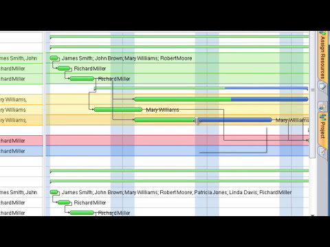
What Information to be Displayed in the ConceptDraw PROJECT Gantt Chart View

Process Flowchart


How To use House Plan Software


How to Create Gantt Chart

 Network Layout Floor Plans
Network Layout Floor Plans solution extends ConceptDraw PRO software functionality with powerful tools for quick and efficient documentation the network equipment and displaying its location on the professionally designed Network Layout Floor Plans. Never before creation of Network Layout Floor Plans, Network Communication Plans, Network Topologies Plans and Network Topology Maps was not so easy, convenient and fast as with predesigned templates, samples, examples and comprehensive set of vector design elements included to the Network Layout Floor Plans solution. All listed types of plans will be a good support for the future correct cabling and installation of network equipment.
 Infographics Area
Solutions of the area What is Infographics from ConceptDraw Solution Park collect templates, samples and vector stencils libraries with design elements for the drawing information graphics.
 Plumbing and Piping Plans
Plumbing and Piping Plans solution extends ConceptDraw PRO v10.2.2 software with samples, templates and libraries of pipes, plumbing, and valves design elements for developing of water and plumbing systems, and for drawing Plumbing plan, Piping plan, PVC Pipe plan, PVC Pipe furniture plan, Plumbing layout plan, Plumbing floor plan, Half pipe plans, Pipe bender plans.
Fishbone Diagram Problem Solving

 Seating Plans
The correct and convenient arrangement of tables, chairs and other furniture in auditoriums, theaters, cinemas, banquet halls, restaurants, and many other premises and buildings which accommodate large quantity of people, has great value and in many cases requires drawing detailed plans. The Seating Plans Solution is specially developed for their easy construction.
- Timeline Indicating Key Targets And Deadlines Of A Business
- Timelines Indicating Key Targets And Deadlines In A Business
- Timelines Indicating Targetsand Deadlines Of A Business
- Business Timeline Indicating Key Targets And Deadlines Example
- Timelines Indicating Key Targets And Deadline
- Timelines Indicating Key Targets And Deadlines For Restaurant
- Examples Of Timelines Indicating Key Targets And Deadlines
- Example Of A Timelines Indicating Key Targets And Deadlines
- Example Timelines Indicating Key Targets And Deadline
- Example Of A Timeline Indicating Key Targets And Deadlines
- Timelines Indicating Key Targets And Deadlines Of Engineering
- Draw Timeline And Indicating Key Targets And Deadline
- Business Timeline Indicating Key Target And Deadlines
- Example Of Timelines Indicating Key Targets And Deadline
- Timelines Indicating Ket Target And Deadline Of A Business
- A Bussiness Timeline Indicating Key Targets And Deadlines
- Timeline Indicating Key Target And Deadlines In Business Plan
- Picture Of Timeline Indicating Key Targets And Deadlines In A ...
- Timelines Indicating Key Target And Deadlines For A Business