The vector stencils library "Requirement diagram" contains 21 SysML symbols.
Use it to design your requirement diagrams using ConceptDraw PRO diagramming and vector drawing software.
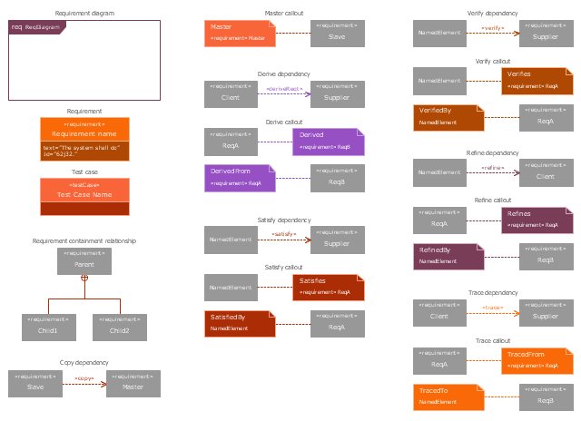
"A requirement specifies a capability or condition that must (or should) be satisfied. A requirement may specify a function that a system must perform or a performance condition a system must achieve. SysML provides modeling constructs to represent text-based requirements and relate them to other modeling elements. The requirements diagram described in this clause can depict the requirements in graphical, tabular, or tree structure format. A requirement can also appear on other diagrams to show its relationship to other modeling elements. The requirements modeling constructs are intended to provide a bridge between traditional requirements management tools and the other SysML models.
A requirement is defined as a stereotype of UML Class subject to a set of constraints. A standard requirement includes properties to specify its unique identifier and text requirement. Additional properties such as verification status, can be specified by the user.
Several requirements relationships are specified that enable the modeler to relate requirements to other requirements as well as to other model elements. These include relationships for defining a requirements hierarchy, deriving requirements, satisfying requirements, verifying requirements, and refining requirements." [www.omg.org/ spec/ SysML/ 1.3/ PDF]
The SysML shapes example "Design elements - Requirement diagram" is included in the SysML solution from the Software Development area of ConceptDraw Solution Park.
Use it to design your requirement diagrams using ConceptDraw PRO diagramming and vector drawing software.
"A requirement specifies a capability or condition that must (or should) be satisfied. A requirement may specify a function that a system must perform or a performance condition a system must achieve. SysML provides modeling constructs to represent text-based requirements and relate them to other modeling elements. The requirements diagram described in this clause can depict the requirements in graphical, tabular, or tree structure format. A requirement can also appear on other diagrams to show its relationship to other modeling elements. The requirements modeling constructs are intended to provide a bridge between traditional requirements management tools and the other SysML models.
A requirement is defined as a stereotype of UML Class subject to a set of constraints. A standard requirement includes properties to specify its unique identifier and text requirement. Additional properties such as verification status, can be specified by the user.
Several requirements relationships are specified that enable the modeler to relate requirements to other requirements as well as to other model elements. These include relationships for defining a requirements hierarchy, deriving requirements, satisfying requirements, verifying requirements, and refining requirements." [www.omg.org/ spec/ SysML/ 1.3/ PDF]
The SysML shapes example "Design elements - Requirement diagram" is included in the SysML solution from the Software Development area of ConceptDraw Solution Park.
SysML requirement diagram symbols
Product Planning
IDEF9 Standard

Data modeling with ConceptDraw DIAGRAM

Use this cloud design pattern template to design your Azure architecture diagrams with ConceptDraw PRO software.
This template was drawn on the base of the diagram in the article "Backends for Frontends pattern" from the Microsoft Azure website.
"The backend service becomes a general-purpose backend, serving the requirements of both the desktop and mobile interfaces.
But the capabilities of a mobile device differ significantly from a desktop browser, in terms of screen size, performance, and display limitations. As a result, the requirements for a mobile application backend differ from the desktop web UI.
These differences result in competing requirements for the backend.
Solution.
Create one backend per user interface. Fine tune the behavior and performance of each backend to best match the needs of the frontend environment, without worrying about affecting other frontend experiences." [docs.microsoft.com/ en-us/ azure/ architecture/ patterns/ backends-for-frontends]
The Azure architecture diagram template "Backends for Frontends pattern" is included in Azure Architecture solution from Computer and Networks area of ConceptDraw Solution Park.

Jacobson Use Cases Diagram

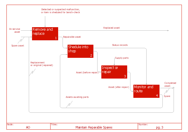
"IDEF0 may be used to model a wide variety of automated and non-automated systems. For new systems, it may be used first to define the requirements and specify the functions, and then to design an implementation that meets the requirements and performs the functions. For existing systems, IDEF0 can be used to analyze the functions the system performs and to record the mechanisms (means) by which these are done. The result of applying IDEF0 to a system is a model that consists of a hierarchical series of diagrams, text, and glossary cross-referenced to each other. The two primary modeling components are functions (represented on a diagram by boxes) and the data and objects that inter-relate those functions (represented by arrows)." [IDEF0. Wikipedia]
The IDEF0 diagram example "Maintain reparable spares" was created using the ConceptDraw PRO diagramming and vector drawing software extended with the IDEF0 Diagrams solution from the Software Development area of ConceptDraw Solution Park.
The IDEF0 diagram example "Maintain reparable spares" was created using the ConceptDraw PRO diagramming and vector drawing software extended with the IDEF0 Diagrams solution from the Software Development area of ConceptDraw Solution Park.
IDEF0 diagram
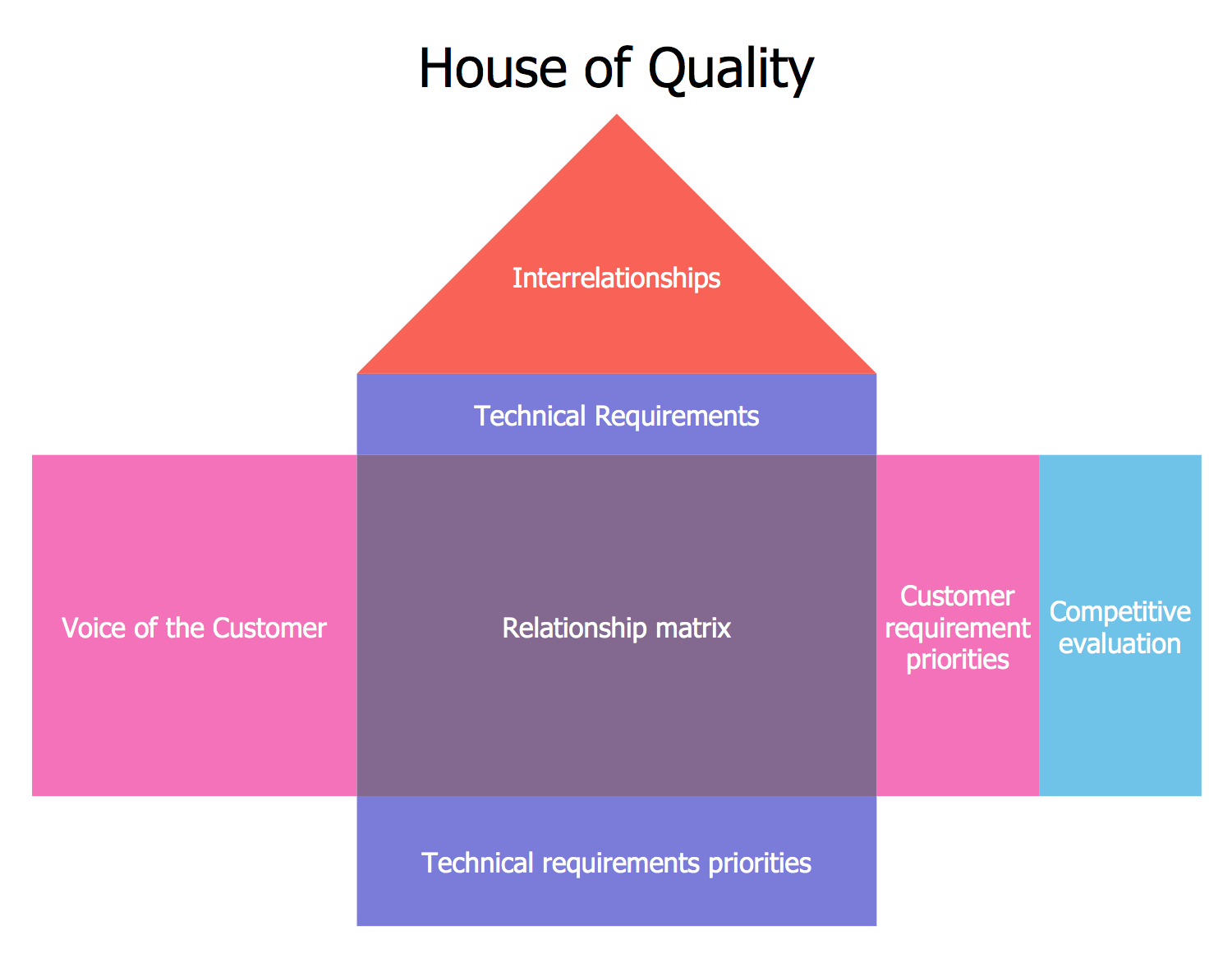
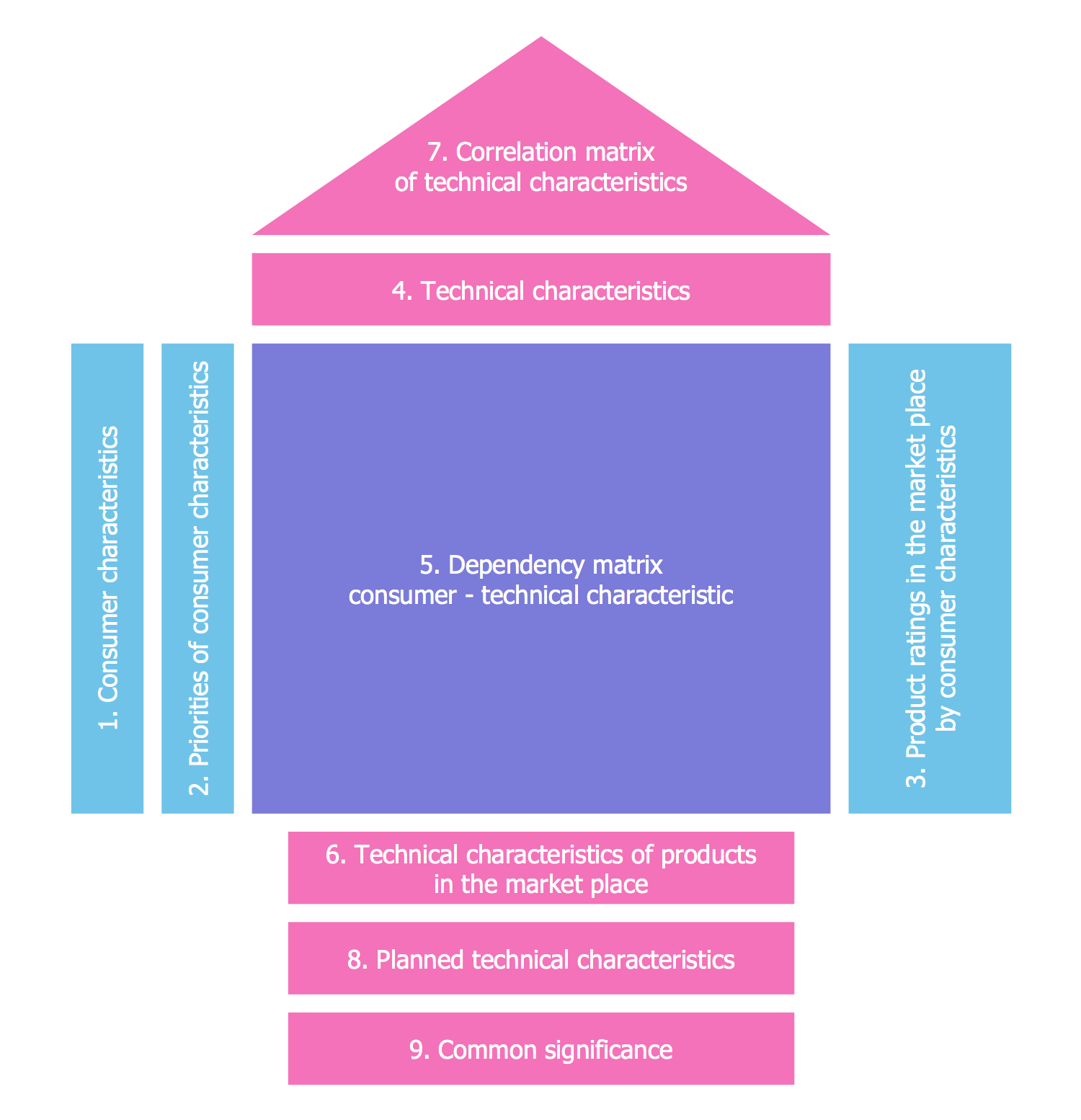
QFD | Quality Function Deployment Diagram
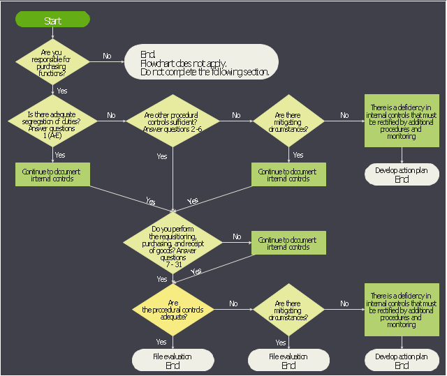
This accounting flowchart example was created on the base of the figure from the website of the Office of the State Comptroller. [osc.ct.gov/ manuals/ acctdirect/ question03.htm]
"Purchasing is the formal process of buying goods and services. The purchasing process can vary from one organization to another, but there are some common key elements.
The process usually starts with a demand or requirements – this could be for a physical part (inventory) or a service. A requisition is generated, which details the requirements (in some cases providing a requirements speciation) which actions the procurement department. A request for proposal (RFP) or request for quotation (RFQ) is then raised. Suppliers send their quotations in response to the RFQ, and a review is undertaken where the best offer (typically based on price, availability and quality) is given the purchase order." [Purchasing process. Wikipedia]
The accounting flowchart example "Purchasing flowchart" was created using the ConceptDraw PRO software extended with the Accounting Flowcharts solution from the Finance and Accounting area of ConceptDraw Solution Park.
Accounting flowchart
- Requirements And Layouts Of A Small Coffee Shop
- Network Layout Floor Plans | The Requirements For And Layout Of ...
- Aerospace and Transport | The Requirements And Layout Of A ...
- Gym Floor Plan | Building Design Package | The Requirements And ...
- Building Design Package | The Requirements And Layout Of The ...
- Cafe and Restaurant Floor Plans | The Requirements Of Small ...
- Aerospace and Transport | The Requirements And Layouts Of A ...
- The Requirements For And Layout Of A Small First Aid Room For ...
- The Requirements And Layouts Of Small First Aid Room For Two
- Building Design Package | Requirements And Layouts Of The ...