 Network Layout Floor Plans
Network Layout Floor Plans solution extends ConceptDraw DIAGRAM software functionality with powerful tools for quick and efficient documentation the network equipment and displaying its location on the professionally designed Network Layout Floor Plans. Never before creation of Network Layout Floor Plans, Network Communication Plans, Network Topologies Plans and Network Topology Maps was not so easy, convenient and fast as with predesigned templates, samples, examples and comprehensive set of vector design elements included to the Network Layout Floor Plans solution. All listed types of plans will be a good support for the future correct cabling and installation of network equipment.
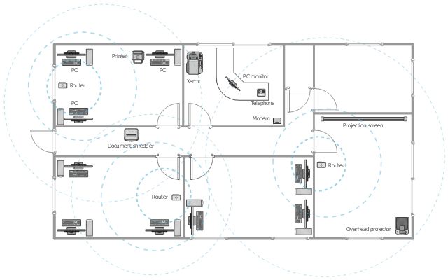
This office floor plan sample depicts the equipment layout of wireless computer network.
"A wireless local area network (WLAN) links two or more devices using some wireless distribution method (typically spread-spectrum or OFDM radio), and usually providing a connection through an access point to the wider Internet. This gives users the ability to move around within a local coverage area and still be connected to the network. Most modern WLANs are based on IEEE 802.11 standards, marketed under the Wi-Fi brand name." [Wireless LAN. Wikipedia]
The equipment layout example "Office wireless network plan" was created using the ConceptDraw DIAGRAM diagramming and vector drawing software extended with the Office Layout Plans solution from the Building Plans area of ConceptDraw Solution Park.
Equipment layout
 Office Layout Plans
Office layouts and office plans are a special category of building plans and are often an obligatory requirement for precise and correct construction, design and exploitation office premises and business buildings. Designers and architects strive to make office plans and office floor plans simple and accurate, but at the same time unique, elegant, creative, and even extraordinary to easily increase the effectiveness of the work while attracting a large number of clients.
Interior Design. Office Layout Plan Design Element


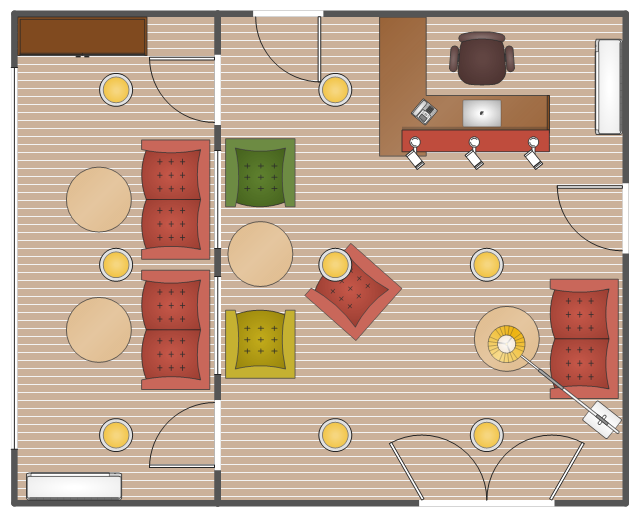
This office reception floorplan sample shows furniture and office supplies layout.
"The front office or reception is an area where visitors arrive and first encounter a staff at a place of business. Front office staff will deal with whatever question the visitor has, and put them in contact with a relevant person at the company. Broadly speaking, the front office includes roles that affect the revenues of the business." [Front office. Wikipedia]
The floorplan example "Office reception plan" was created using ConceptDraw DIAGRAM software extended with Office Layout Plan solition from Building Plan area of ConceptDraw Solution Park.
Layout example
The vector stencils library "Network layout floorplan" contain 34 symbol icons for drawing computer network floor plans, communication equipment layouts, and structured cabling diagrams.
"Structured cabling is building or campus telecommunications cabling infrastructure that consists of a number of standardized smaller elements (hence structured) called subsystems. ...
Structured cabling design and installation is governed by a set of standards that specify wiring data centers, offices, and apartment buildings for data or voice communications using various kinds of cable, most commonly category 5e (CAT-5e), category 6 (CAT-6), and fibre optic cabling and modular connectors. These standards define how to lay the cabling in various topologies in order to meet the needs of the customer, typically using a central patch panel (which is normally 19 inch rack-mounted), from where each modular connection can be used as needed. Each outlet is then patched into a network switch (normally also rack-mounted) for network use or into an IP or PBX (private branch exchange) telephone system patch panel." [Structured cabling. Wikipedia]
The design elements example "Network layout floorplan - Vector stencils library" was created using the ConceptDraw PRO diagramming and vector drawing software extended with the Network Layout Floor Plans solution from the Computer and Networks area of ConceptDraw Solution Park.
PC

Scanner

Switch

Router

Modem

Hub

Rack Mount

Printer

Floor Mounted Outlet

Single Outlet

Duplex Outlet

Direct bus cable

Tops or bottoms bus cable

Side to side bus cable

Multi-tree bus cable

Bottom to side bus cable

Sides bus cable

Door

Door, threshold

Door, stop

Door, stop, threshold

Door, frame

Door, frame, threshold

Door, frame, stop

Door, frame, stop, threshold

Window

Window, sill

Window, sash

Window, sash, sill

Window, frame

Window, frame, sill

Window, frame, sash

Window, frame, sash, sill

How To use House Electrical Plan Software


 Telecommunication Network Diagrams
Telecommunication Network Diagrams solution extends ConceptDraw DIAGRAM software with samples, templates, and great collection of vector stencils to help the specialists in a field of networks and telecommunications, as well as other users to create Computer systems networking and Telecommunication network diagrams for various fields, to organize the work of call centers, to design the GPRS networks and GPS navigational systems, mobile, satellite and hybrid communication networks, to construct the mobile TV networks and wireless broadband networks.
This office floor plan sample depicts the equipment layout of wireless computer network.
"A wireless local area network (WLAN) links two or more devices using some wireless distribution method (typically spread-spectrum or OFDM radio), and usually providing a connection through an access point to the wider Internet. This gives users the ability to move around within a local coverage area and still be connected to the network. Most modern WLANs are based on IEEE 802.11 standards, marketed under the Wi-Fi brand name." [Wireless LAN. Wikipedia]
The equipment layout example "Office wireless network plan" was created using the ConceptDraw DIAGRAM diagramming and vector drawing software extended with the Office Layout Plans solution from the Building Plans area of ConceptDraw Solution Park.
"A wireless local area network (WLAN) links two or more devices using some wireless distribution method (typically spread-spectrum or OFDM radio), and usually providing a connection through an access point to the wider Internet. This gives users the ability to move around within a local coverage area and still be connected to the network. Most modern WLANs are based on IEEE 802.11 standards, marketed under the Wi-Fi brand name." [Wireless LAN. Wikipedia]
The equipment layout example "Office wireless network plan" was created using the ConceptDraw DIAGRAM diagramming and vector drawing software extended with the Office Layout Plans solution from the Building Plans area of ConceptDraw Solution Park.
Equipment layout
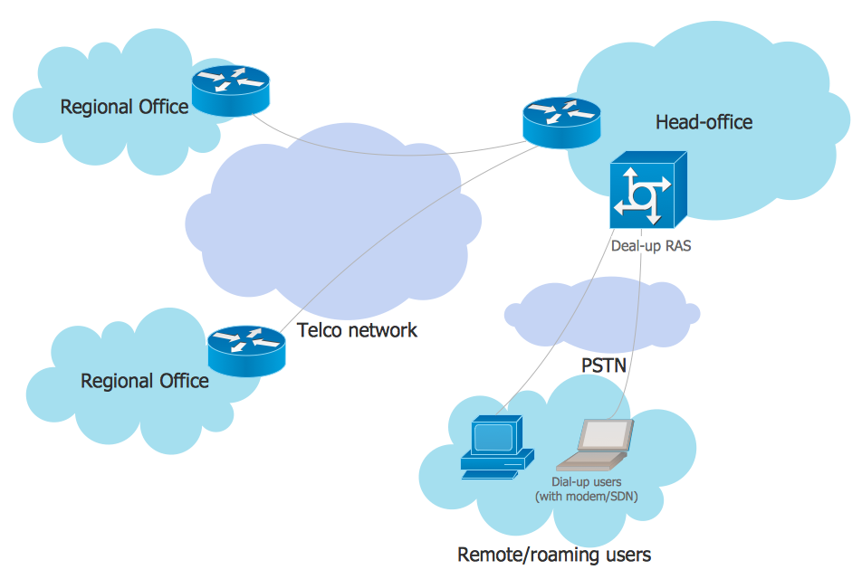
EPN Frame-Relay and Dial-up Network. Computer and Network Examples

- Sample Design Plan Of Telephone Layout
- Design elements - Office equipment | Office equipment - Vector ...
- Network Layout | Office wireless network plan | Network layout ...
- How To Draw A Office Phone
- Lighting and switch layout | Classroom lighting - Reflected ceiling ...
- Drawing Office Phone With Label
- Catv Layout
- Design elements - Cable TV (CATV) | Cable TV - Vector stencils ...
- Interior Design Office Layout Plan Design Element | Office ...
- How to Draw a Floor Plan for Your Office | Illustration | Office Layout ...