 SYSML
SYSML
The SysML solution helps to present diagrams using Systems Modeling Language; a perfect tool for system engineering.
SysML

HelpDesk
How to Create a SysML Diagram

Data Modeling Diagram

SysML Diagram
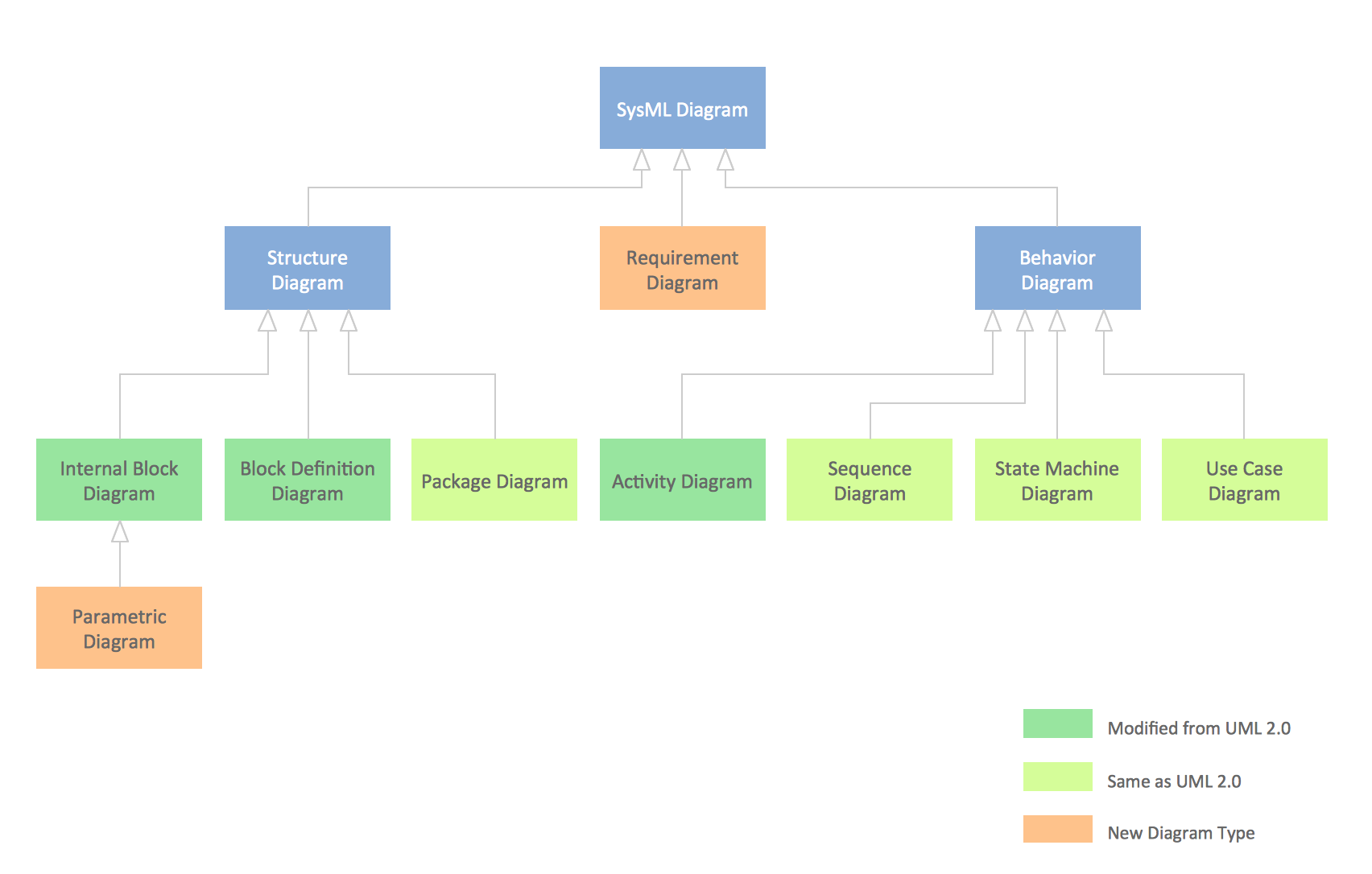
UML Diagram


This vector stencils library contains 54 BDD symbols.
Use it to design your block definition diagrams using ConceptDraw PRO diagramming and vector drawing software.
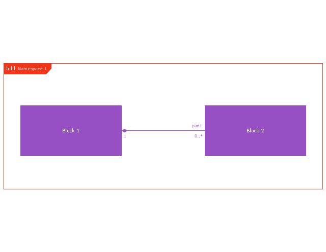
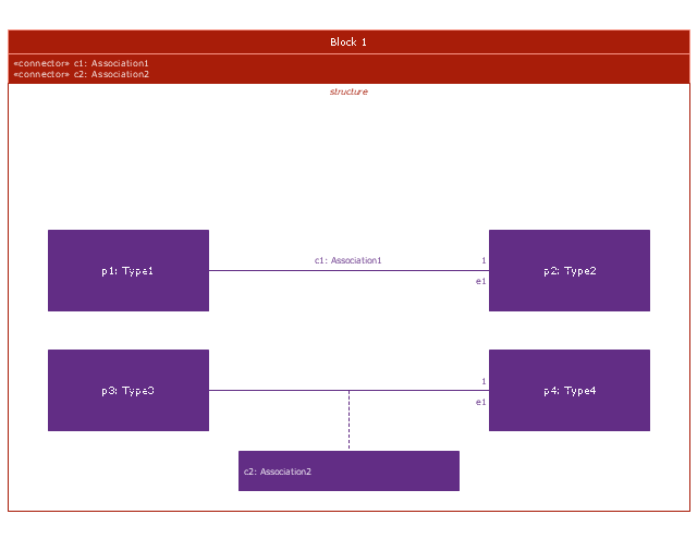
"Block Definition Diagram
A block definition diagram is based on the UML class diagram, with restrictions and extensions as defined by SysML. ...
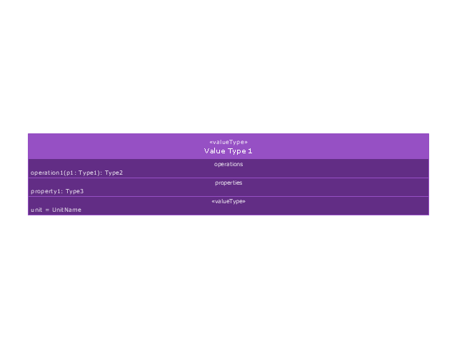
Block and ValueType Definitions
A SysML Block defines a collection of features to describe a system or other element of interest. A SysML ValueType
defines values that may be used within a model. SysML blocks are based on UML classes, as extended by UML composite structures. SysML value types are based on UML data types. Diagram extensions for SysML blocks and value types are described by other subheadings of this sub clause." [www.omg.org/ spec/ SysML/ 1.3/ PDF]
The vector stencils library "Block definition diagram" is included in the SysML solution from the Software Development area of ConceptDraw Solution Park.
Use it to design your block definition diagrams using ConceptDraw PRO diagramming and vector drawing software.
"Block Definition Diagram
A block definition diagram is based on the UML class diagram, with restrictions and extensions as defined by SysML. ...
Block and ValueType Definitions
A SysML Block defines a collection of features to describe a system or other element of interest. A SysML ValueType
defines values that may be used within a model. SysML blocks are based on UML classes, as extended by UML composite structures. SysML value types are based on UML data types. Diagram extensions for SysML blocks and value types are described by other subheadings of this sub clause." [www.omg.org/ spec/ SysML/ 1.3/ PDF]
The vector stencils library "Block definition diagram" is included in the SysML solution from the Software Development area of ConceptDraw Solution Park.
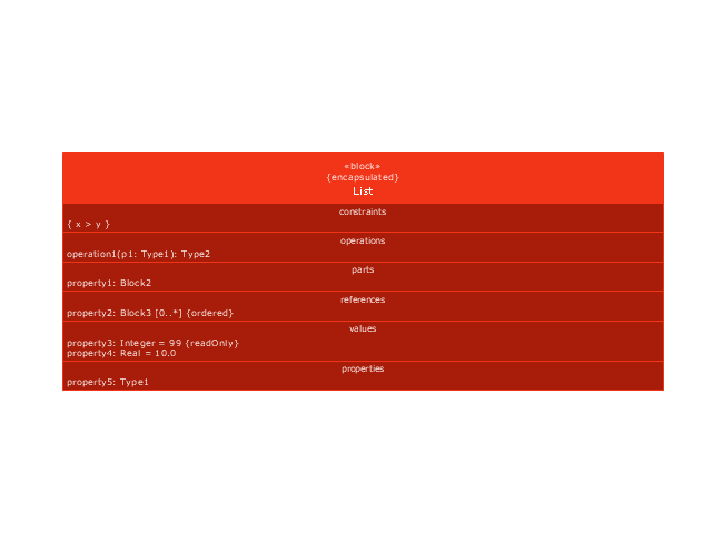
Block definition diagram
Block
Actor

Actor 2

Value type
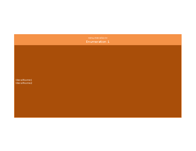
Enumeration
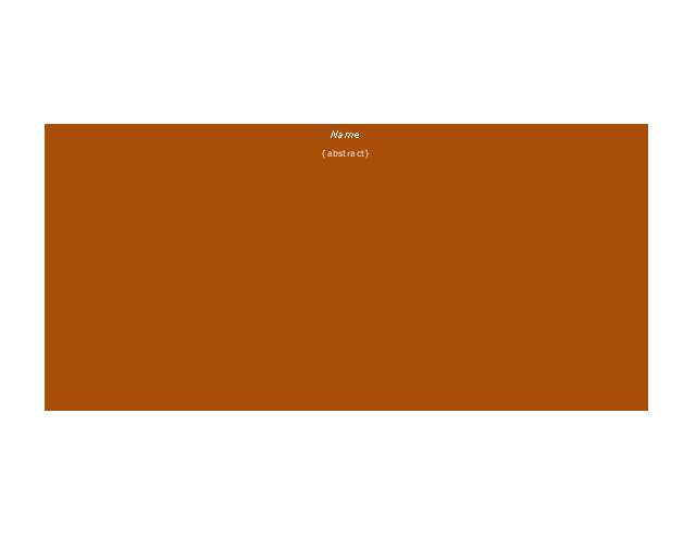
Abstract definition

Abstract definition 2
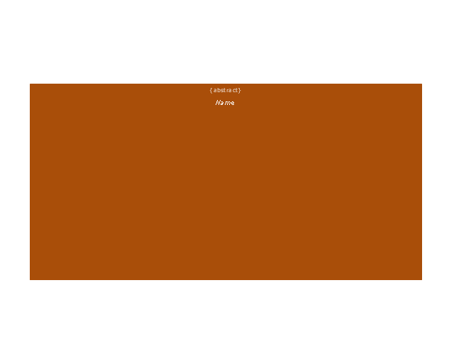
Abstract definition 3
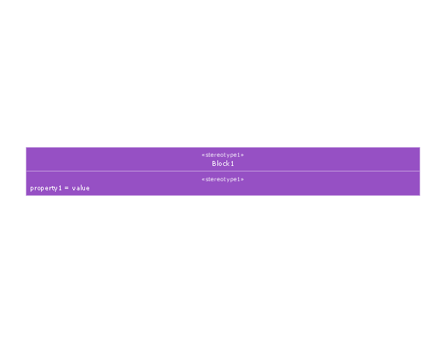
Stereotype property compartment
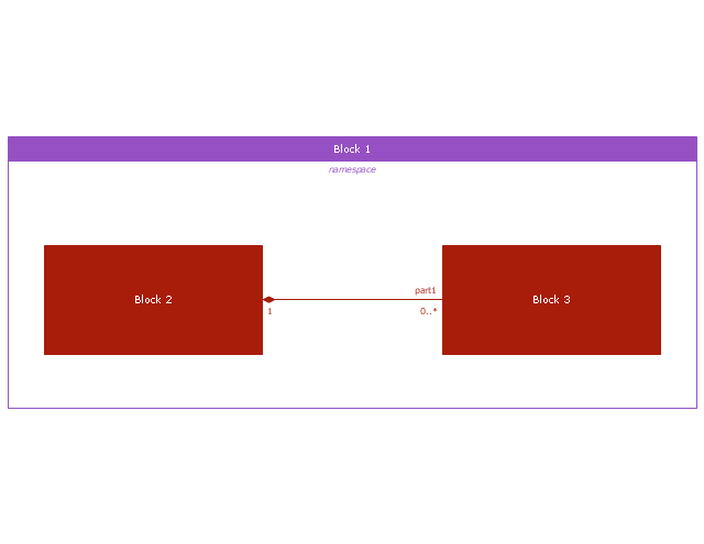
Namespace compartment
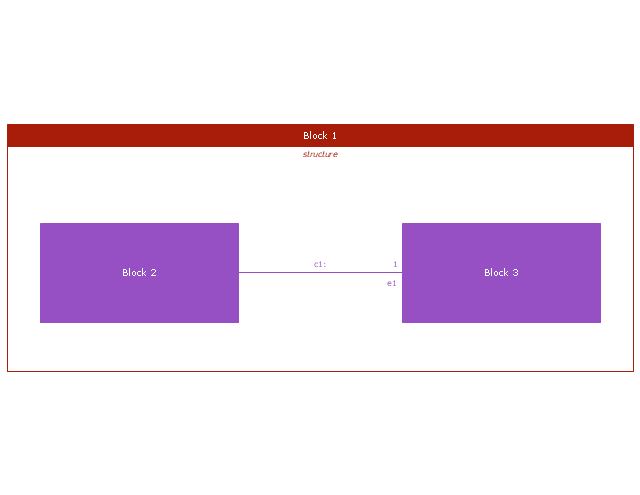
Structure compartment
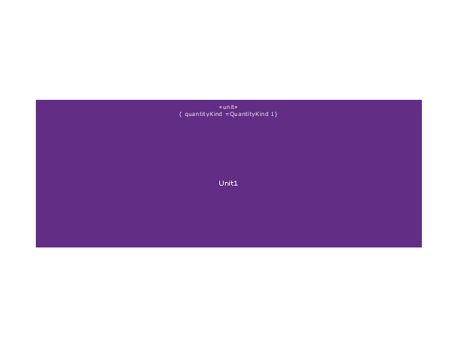
Unit
Unit 2
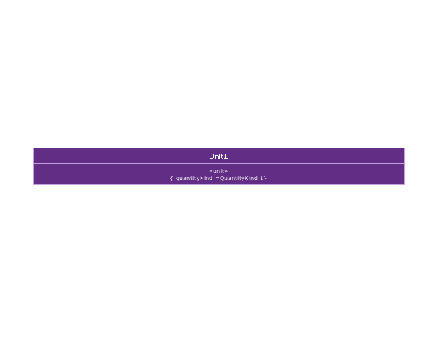
Quantity kind

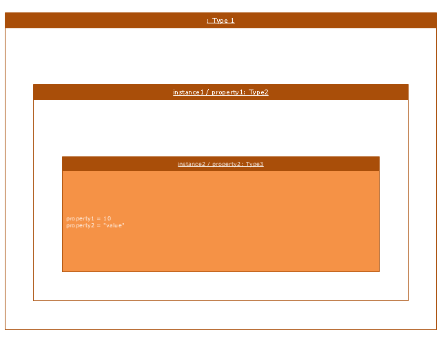
Instance specification
Instance specification 2
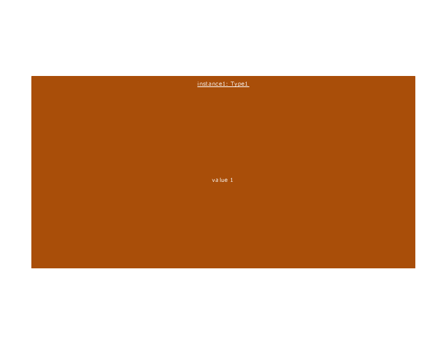
Instance specification 3
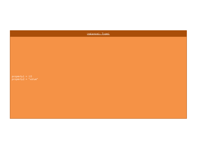
Instance specification 4
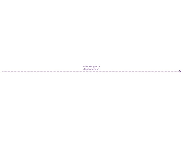
Dependency
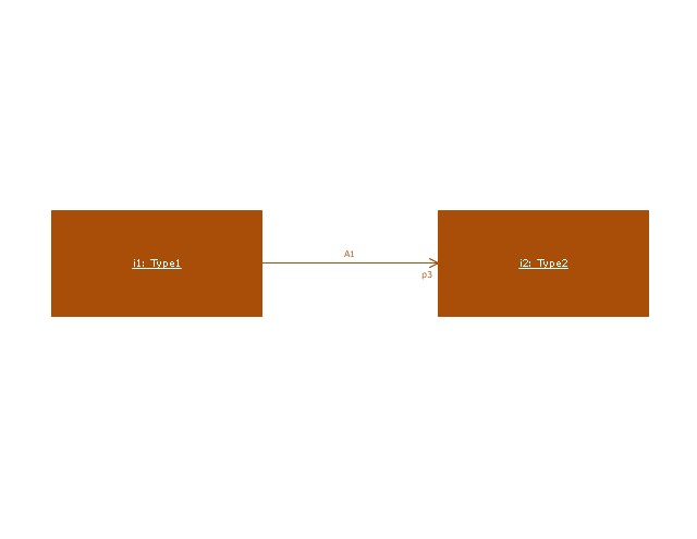
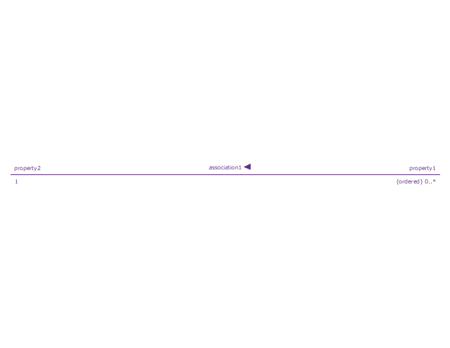
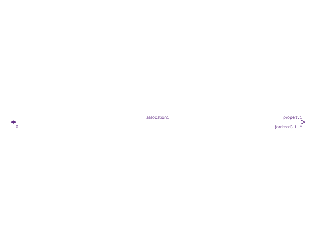
Reference association
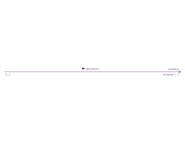
Reference association 2
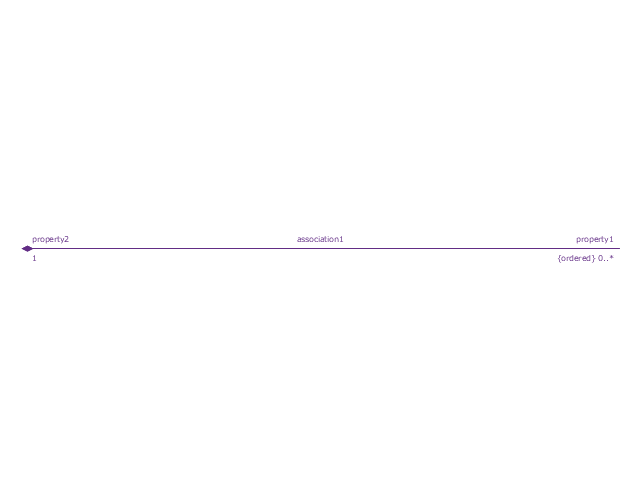
Part association
Part association 2
Shared association
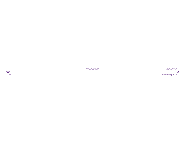
Shared association 2

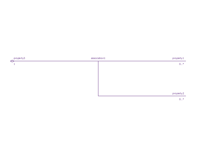
Multibranch part association
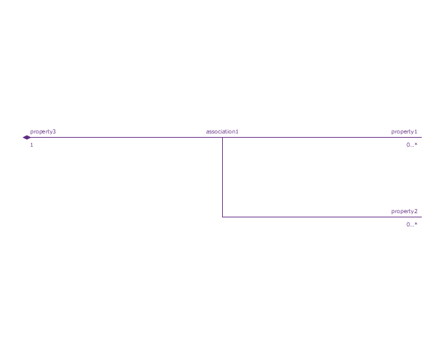
Multibranch shared association
Generalization

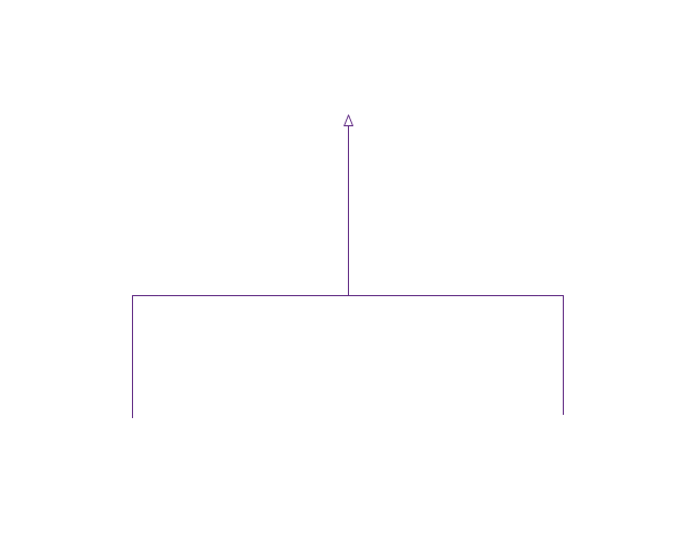
Multibranch generalization
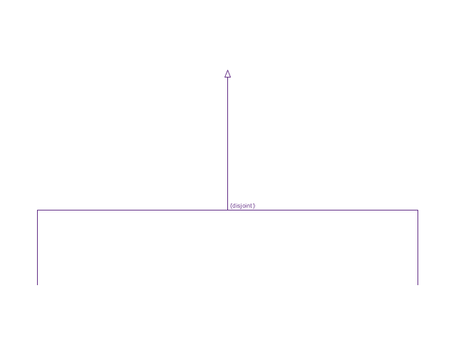
Generalization set, disjoint
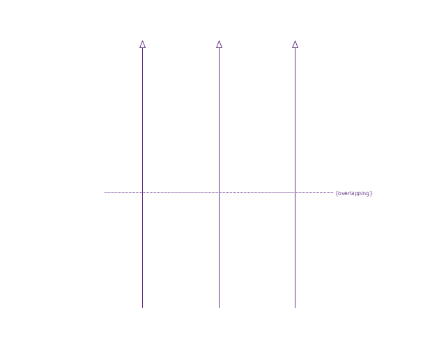
Generalization set, overlapping
Block namespace containment
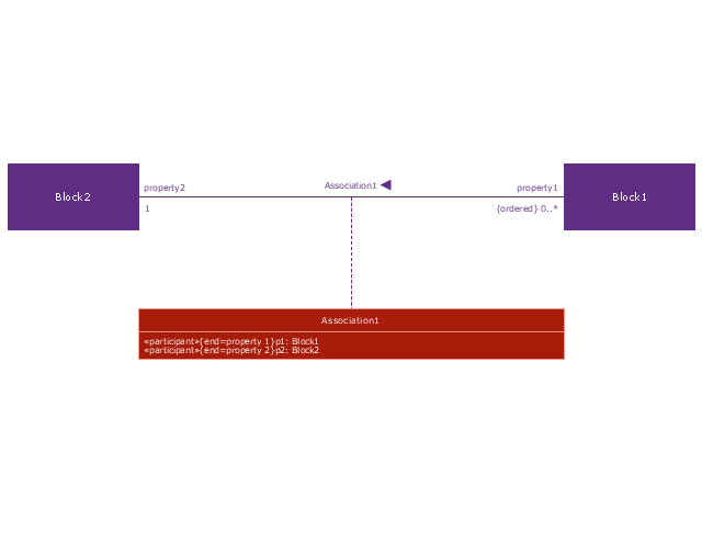
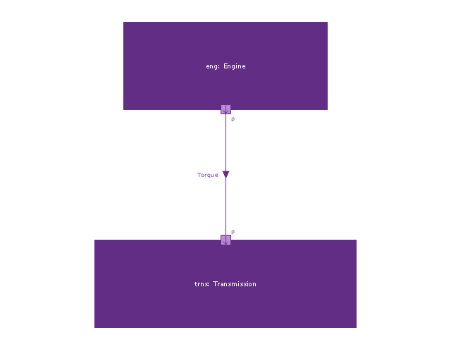
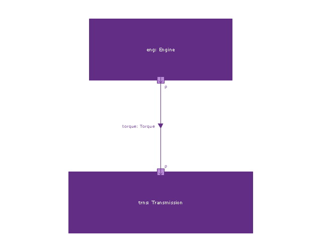
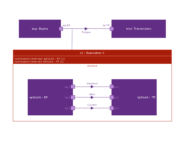
Participant property
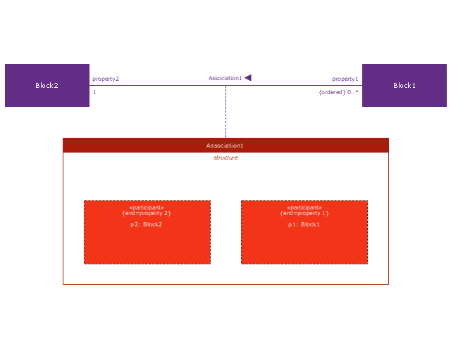
Participant property 2
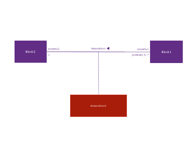
Participant property 3
Connector property
Conjugated ports

Conjugated ports 2

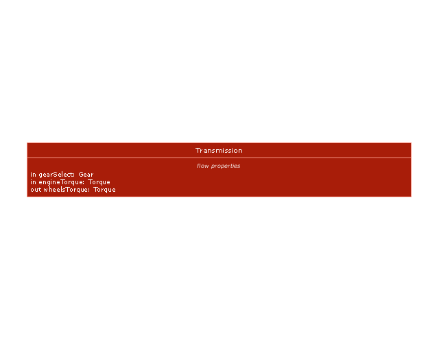
Ports with flow properties

Port (compartment notation)
-vector-stencils-library---block-definition-diagram.png--diagram-flowchart-example.png)
Port (nested)
-vector-stencils-library---block-definition-diagram.png--diagram-flowchart-example.png)
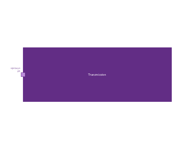
Proxy port
Full port

Flow property
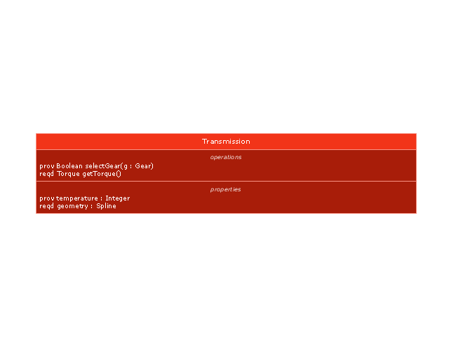
Required and provided features
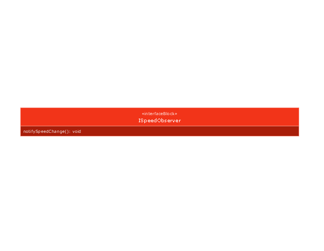
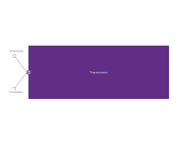
Interface block
Item flow
Item flow 2
Item flow 3
Interface
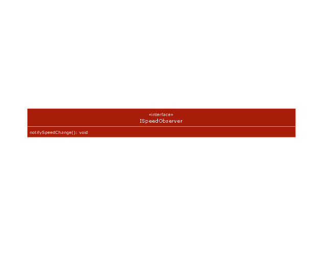
Required and provided interfaces

Required and provided interfaces 2
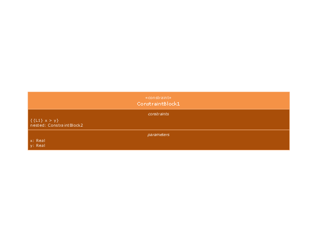
Constraint block
 Business Process Model and Notation
Business Process Model and Notation Solution for ConceptDraw DIAGRAM is helpful for modeling the business processes of any degree of complexity, documenting them and effective creating diagrams using the BPMN 2.0 standard.
UML Class Diagram Generalization Example UML Diagrams

- Basic Pie Charts | Business Process Model and Notation | SYSML ...
- SYSML | Business Process Model and Notation | ATM UML ...
- How to Create a SysML Diagram Using ConceptDraw PRO | How to ...
- Entity-Relationship Diagram (ERD) | SYSML | Business Process ...
- SYSML | Atm Class Diagram With Attributes And Operations
- Diagramme Sysml
- SysML Diagram | Diagramming Software for Design UML ...
- SYSML | How to Create a SysML Diagram Using ConceptDraw PRO ...
- Settlement Process Flowchart. Flowchart Examples | Jacobson Use ...
- SysML block definition diagram - Function Breakdown model | Event ...