Mechanical Drawing Symbols

Mechanical Design Software

 Mechanical Engineering
This solution extends ConceptDraw DIAGRAM.9 mechanical drawing software (or later) with samples of mechanical drawing symbols, templates and libraries of design elements, for help when drafting mechanical engineering drawings, or parts, assembly, pneumatic,
Electrical Symbols, Electrical Schematic Symbols

Mechanical Engineering

CAD Drawing Software for Making Mechanic Diagram and Electrical Diagram Architectural Designs


The vector stencils library "Dimensioning and tolerancing" contains 45 symbols of geometric dimensions and mechanical tolerances, geometric symbols, callouts, and text boxes and inserts.
Use these geometric dimensioning and tolerancing (GD&T) shapes to create annotated mechanical drawings.
"Geometric dimensioning and tolerancing (GD&T) is a system for defining and communicating engineering tolerances. It uses a symbolic language on engineering drawings and computer-generated three-dimensional solid models that explicitly describes nominal geometry and its allowable variation. It tells the manufacturing staff and machines what degree of accuracy and precision is needed on each controlled feature of the part. GD&T is used to define the nominal (theoretically perfect) geometry of parts and assemblies, to define the allowable variation in form and possible size of individual features, and to define the allowable variation between features." [Geometric dimensioning and tolerancing. Wikipedia]
The shapes example "Design elements - Dimensioning and tolerancing" was created using the ConceptDraw PRO diagramming and vector drawing software extended with the Mechanical Engineering solution from the ConceptDraw Solution Park.
Dimensioning and tolerancing symbols

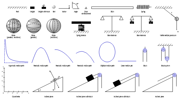
The vector stencils library "Mechanics" contains 29 symbol shapes for drawing mechanics experiment schemes and physical diagrams.
"Mechanics ... is the branch of science concerned with the behavior of physical bodies when subjected to forces or displacements, and the subsequent effects of the bodies on their environment. The scientific discipline has its origins in Ancient Greece with the writings of Aristotle and Archimedes. During the early modern period, scientists such as Galileo, Kepler, and especially Newton, laid the foundation for what is now known as classical mechanics. It is a branch of classical physics that deals with particles that are either at rest or are moving with velocities significantly less than the speed of light. It can also be defined as a branch of science which deals with the motion of and forces on objects." [Mechanics. Wikipedia]
The example "Design elements - Mechanics" was created using the ConceptDraw PRO diagramming and vector drawing software extended with the Physics solution from the Science and Education area of ConceptDraw Solution Park.
Mechanical symbols
SDL Flowchart Symbols

The vector stencils library "Pumps" contains 82 symbols of pumps, compressors, fans, turbines, and power generators.
Use these icons to design pumping systems, air and fluid compression systems, and industrial process diagrams.
"A pump is a device that moves fluids (liquids or gases), or sometimes slurries, by mechanical action. Pumps can be classified into three major groups according to the method they use to move the fluid: direct lift, displacement, and gravity pumps.
Pumps operate by some mechanism (typically reciprocating or rotary), and consume energy to perform mechanical work by moving the fluid. Pumps operate via many energy sources, including manual operation, electricity, engines, or wind power, come in many sizes, from microscopic for use in medical applications to large industrial pumps.
Mechanical pumps serve in a wide range of applications such as pumping water from wells, aquarium filtering, pond filtering and aeration, in the car industry for water-cooling and fuel injection, in the energy industry for pumping oil and natural gas or for operating cooling towers. In the medical industry, pumps are used for biochemical processes in developing and manufacturing medicine, and as artificial replacements for body parts, in particular the artificial heart and penile prosthesis.
In biology, many different types of chemical and bio-mechanical pumps have evolved, and biomimicry is sometimes used in developing new types of mechanical pumps." [Pump. Wikipedia]
The example "Design elements - Pumps" was created using the ConceptDraw PRO diagramming and vector drawing software extended with the Chemical and Process Engineering solution from the Engineering area of ConceptDraw Solution Park.
Pump symbols

Cisco Buildings. Cisco icons, shapes, stencils and symbols

Electrical Symbols, Electrical Diagram Symbols

The vector stencil library "HVAC ductwork" contains 63 duct and vent symbols.
Use it for drawing HVAC system diagrams, heating, ventilation, air conditioning, refrigeration, automated building control, and environmental control design floor
plans and equipment layouts.
"Ducts are used in heating, ventilation, and air conditioning (HVAC) to deliver and remove air. These needed airflows include, for example, supply air, return air, and exhaust air. Ducts also deliver, most commonly as part of the supply air, ventilation air. As such, air ducts are one method of ensuring acceptable indoor air quality as well as thermal comfort.
A duct system is often called ductwork. Planning ('laying out'), sizing, optimizing, detailing, and finding the pressure losses through a duct system is called duct design." [Duct (HVAC). Wikipedia]
The vector stencils example "Design elements - HVAC ductwork" is included in HVAC Plans solution from the Building Plans area of ConceptDraw Solution Park.
HVAC ductwork symbols

The vector stencils library "Heating equipment" contains 42 symbols of regenerators, intercoolers, heaters, and condensers.
Use these shapes for drawing cooling systems, heat recovery systems, thermal, heat transfer and mechanical design, and process flow diagrams (PFD).
"Heating or cooling of processes, equipment, or enclosed environments are within the purview of thermal engineering.
One or more of the following disciplines may be involved in solving a particular thermal engineering problem:
Thermodynamics,
Fluid mechanics,
Heat transfer,
Mass transfer.
Thermal engineering may be practiced by mechanical engineers and chemical engineers.
One branch of knowledge used frequently in thermal engineering is that of thermofluids." [Thermal engineering. Wikipedia]
The design elements example "Heating equipment" was created using the ConceptDraw PRO diagramming and vector drawing software extended with the Chemical and Process Engineering solution from the Engineering area of ConceptDraw Solution Park.
Heating equipment symbols

Electrical Diagram

- Mechanical Drawing Symbols | Mechanical Design Software ...
- Mechanical Drawing Symbols | Mechanical Engineering ...
- Mechanical Drawing Symbols | Mechanical Design Software | CAD ...
- Mechanical Drawing Symbols | Mechanical Drawing Software ...
- Symbol Of Mechanical Engineering Design Pdf
- Design elements - Bearings | Mechanical Drawing Symbols ...
- Mechanical Engineering | Mechanical Design Software | Mechanical ...
- Mechanical Engineering Design Symbols
- Mechanical Engineering Drawing Parts
- Mechanical Design Symbols Used In Parts Design
- Mechanical Drawing Symbols | Mechanical Engineering ...
- Mechanical Designing Symbol
- Mechanical Drawing Symbols | Design elements - Bearings ...
- Welding symbols | Design elements - Welding | Welding - Vector ...
- Mechanical Drawing Symbols | Technical Drawing Software ...
- Mechanical Engineering | Mechanical Drawing Symbols ...
- Engineering Mechanical Design Symbols
- Mechanical Drawing Symbols | Mechanical Engineering ...
- Mechanical Engineering | Mechanical Engineering | Design ...
- Mechanical Drawing Symbols | Technical Drawing Software ...