ERD Symbols and Meanings


Process Flowchart


Basic Flowchart Symbols and Meaning


"The symbols and conventions used in welding documentation are specified in national and international standards such as ISO 2553 Welded, brazed and soldered joints -- Symbolic representation on drawings and ISO 4063 Welding and allied processes -- Nomenclature of processes and reference numbers. The US standard symbols are outlined by the American National Standards Institute and the American Welding Society and are noted as "ANSI/ AWS".
In engineering drawings, each weld is conventionally identified by an arrow which points to the joint to be welded. The arrow is annotated with letters, numbers and symbols which indicate the exact specification of the weld. In complex applications, such as those involving alloys other than mild steel, more information may be called for than can comfortably be indicated using the symbols alone. Annotations are used in these cases." [Symbols and conventions used in welding documentation. Wikipedia]
The example chart "Elements of welding symbol" is redesigned using the ConceptDraw PRO diagramming and vector drawing software from the Wikipedia file: Elements of a welding symbol.PNG.
[en.wikipedia.org/ wiki/ File:Elements_ of_ a_ welding_ symbol.PNG]
The diagram example "Elements location of a welding symbol" is contained in the Mechanical Engineering solution from the Engineering area of ConceptDraw Solution Park.
Welding joint symbol chart

The vector stencils library "Dimensioning and tolerancing" contains 45 symbols of geometric dimensions and mechanical tolerances, geometric symbols, callouts, and text boxes and inserts.
Use these geometric dimensioning and tolerancing (GD&T) shapes to create annotated mechanical drawings.
"Geometric dimensioning and tolerancing (GD&T) is a system for defining and communicating engineering tolerances. It uses a symbolic language on engineering drawings and computer-generated three-dimensional solid models that explicitly describes nominal geometry and its allowable variation. It tells the manufacturing staff and machines what degree of accuracy and precision is needed on each controlled feature of the part. GD&T is used to define the nominal (theoretically perfect) geometry of parts and assemblies, to define the allowable variation in form and possible size of individual features, and to define the allowable variation between features." [Geometric dimensioning and tolerancing. Wikipedia]
The shapes example "Design elements - Dimensioning and tolerancing" was created using the ConceptDraw PRO diagramming and vector drawing software extended with the Mechanical Engineering solution from the ConceptDraw Solution Park.
Dimensioning and tolerancing symbols

Network Diagram Software LAN Network Diagrams & Diagrams for LAN Physical Office Network Diagrams


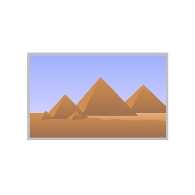
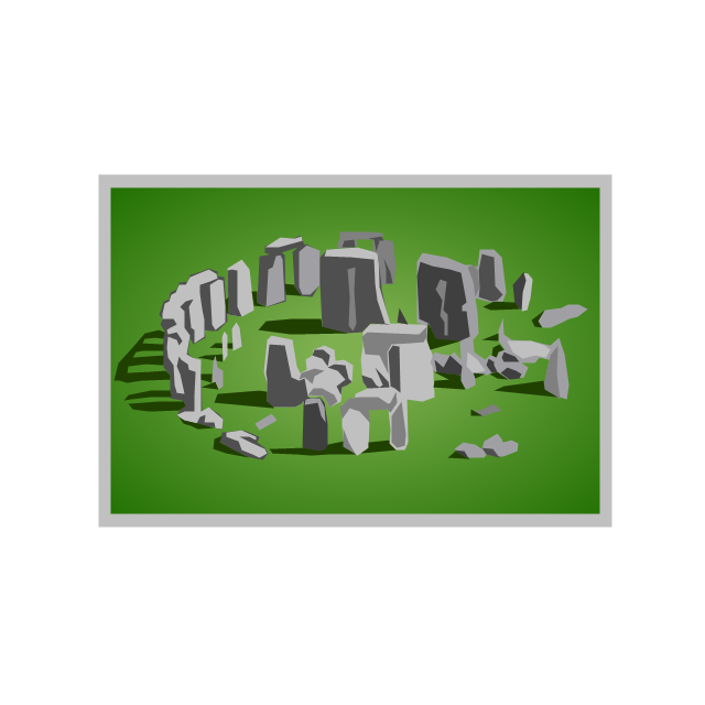
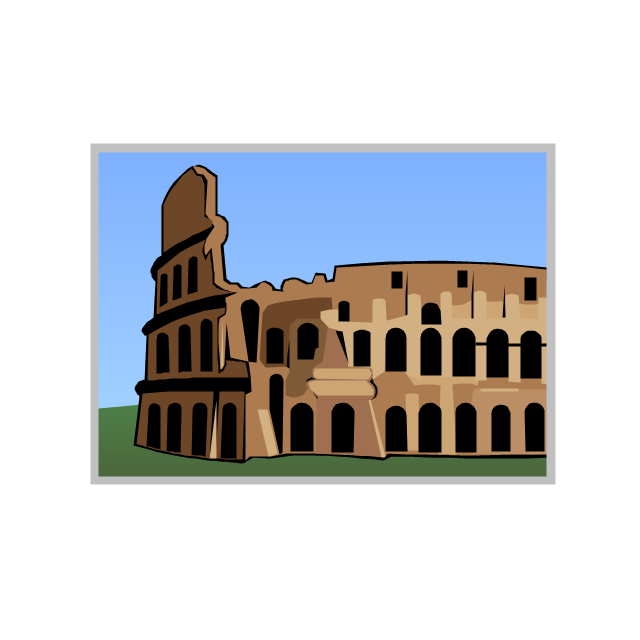
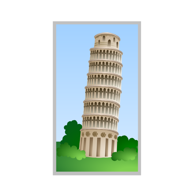
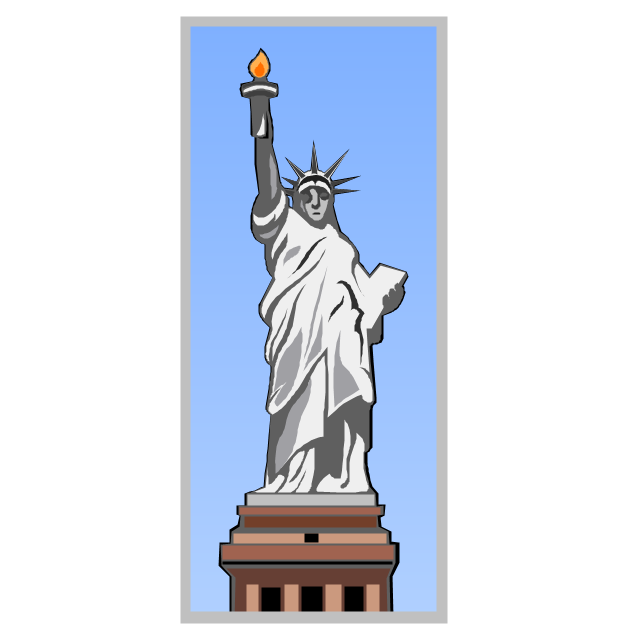
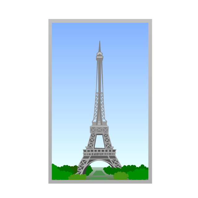
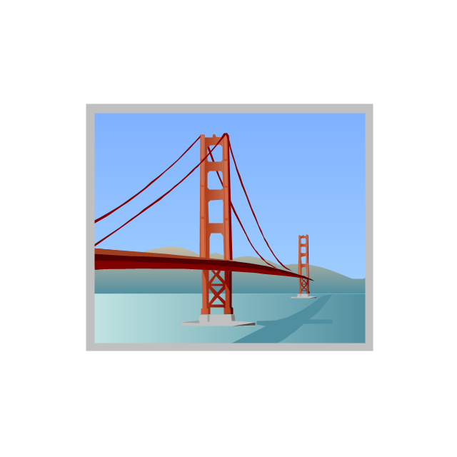
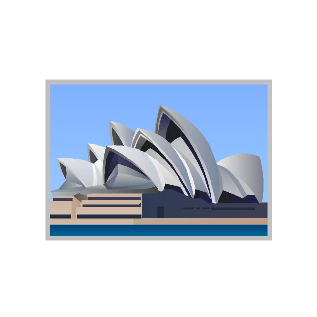
The vector stencils library "Architecture" contains 8 clipart images of some architecture monuments.
"In English the word "monumental" is often used in reference to something of extraordinary size and power, as in monumental sculpture, but also to mean simply anything made to commemorate the dead, as a funerary monument or other example of funerary art. ...
Monuments have been created for thousands of years, and they are often the most durable and famous symbols of ancient civilizations. ...
As societies became organized on a larger scale, so monuments so large as to be difficult to destroy and the Egyptian Pyramids, the Greek Parthenon, the Great Wall of China, Islamic Indian Taj Mahal or the Moai of Easter Island have become symbols of their civilizations. In more recent times, monumental structures such as the Statue of Liberty and Eiffel Tower have become iconic emblems of modern nation-states. The term monumentality relates to the symbolic status and physical presence of a monument." [Monument. Wikipedia]
The example "Architecture - Vector stencils library" was created using the ConceptDraw PRO diagramming and vector drawing software extended with the Artwork solution from the Illustration area of ConceptDraw Solution Park.
www.conceptdraw.com/ solution-park/ illustrations-artwork
Egyptian pyramids
Stonehenge
Colosseum
Leaning Tower of Pisa
Statue of Liberty
Eiffel Tower
Golden Gate
Sydney Opera House
- Mechanical Drawing Symbols | Mechanical Engineering | Elements ...
- Mechanical Drawing Symbols | Mechanical Engineering | Technical ...
- Entity Relationship Diagram Symbols | Data Flow Diagram Symbols ...
- Basic Flowchart Symbols and Meaning | Flowchart design ...
- Mechanical Drawing Symbols | Process Flow Diagram Symbols ...
- Mechanical Drawing Symbols | Mechanical Engineering | Design ...
- Elements location of a welding symbol | Building Drawing
- Mechanical Drawing Symbols | Elements location of a welding ...
- Mechanical Drawing Symbols | Welding symbols | Mechanical ...
- Elements location of a welding symbol | Design elements - Welding ...
- Entity Relationship Diagram Symbols and Meaning ERD Symbols ...
- Mechanical Drawing Symbols | Technical Drawing Software ...
- Mechanical Drawing Symbols | Technical Drawing Software ...
- Data Flow Diagram Symbols . DFD Library | Basic Flowchart ...
- Mechanical Drawing Symbols | Mechanical Engineering ...
- Mechanical Drawing Symbols | Entity Relationship Diagram ...
- Mechanical Drawing Symbols | Mechanical Engineering ...
- Engineering Drawing Symbols And Nomenclature
- Mechanical Drawing Symbols | Basic Flowchart Symbols and ...
- Welding Symbols On Drawings