The vector stencils library "Network layout floorplan" contain 34 symbol icons for drawing computer network floor plans and communication equipment and cabling layouts.
"Networking hardware may also be known as network equipment or computer networking devices. Units which are the last receiver or generate data are called hosts or data terminal equipment.
All these terms refer to devices facilitating the use of a computer network. Specifically, they mediate data in a computer network. ...
Typically, networking hardware includes gateways, routers, network bridges, switches, hubs, and repeaters. But it also includes hybrid network devices such as multilayer switches, protocol converters, bridge routers, proxy servers, firewalls, network address translators, multiplexers, network interface controllers, wireless network interface controllers, modems, ISDN terminal adapters, line drivers, wireless access points, networking cables and other related hardware.
The most common kind of networking hardware today is a copper-based Ethernet adapter because of its standard inclusion on most modern computer systems. Wireless networking has, however, become increasingly popular, especially for portable and handheld devices.
Other hardware prevalent in computer networking includes data center equipment (such as file servers, database servers and storage areas), network services (such as DNS, DHCP, email, etc.) as well as devices which assure content delivery." [Networking hardware. Wikipedia]
The shapes example "Design elements - Network layout floorplan" was created using the ConceptDraw PRO diagramming and vector drawing software extended with the Network Layout Floor Plans solution from the Computer and Networks area of ConceptDraw Solution Park.
Network layout floor plan symbols

Create Floor Plan

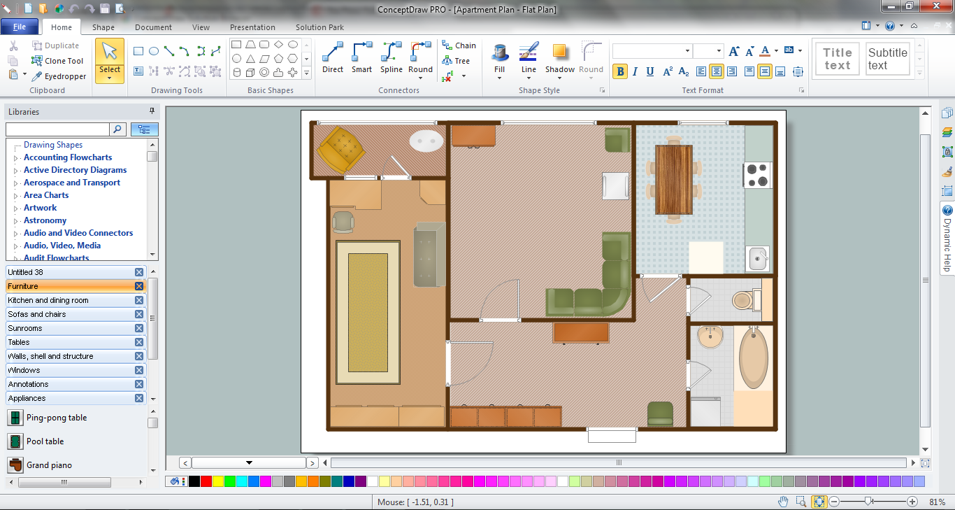
The design elements library Walls, shell and structure contains 29 symbols of structural elements: walls, rooms, windows, doors, pillars.
Use the vector stencils library Walls, shell and structure to draw the floor plans and other architectural drawings, blueprints, home and building interior design, space layout plans, construction and house framing diagrams using the ConceptDraw PRO diagramming and vector drawing software.
"A wall is a horizontal structure, usually solid, that defines and sometimes protects an area. Most commonly, a wall delineates a building and supports its superstructure, separates space in buildings into sections, or protects or delineates a space in the open air. There are three principal types of structural walls: building walls, exterior boundary walls, and retaining walls.
Building walls have one main purpose: to support roofs and ceilings. Such walls most often have three or more separate components. In today's construction, a building wall will usually have the structural elements (such as 2×4 studs in a house wall), insulation, and finish elements or surface (such as drywall or panelling). In addition, the wall may house various types of electrical wiring or plumbing. Electrical outlets are usually mounted in walls.
Building walls frequently become works of art externally and internally, such as when featuring mosaic work or when murals are painted on them; or as design foci when they exhibit textures or painted finishes for effect.
In architecture and civil engineering, the term curtain wall refers to the facade of a building which is not load-bearing but functions as decoration, finish, front, face, or history preservation." [Wall. Wikipedia]
This shapes library Walls, shell and structure is provided by the Floor Plans solution from the Building Plans area of ConceptDraw Solution Park.

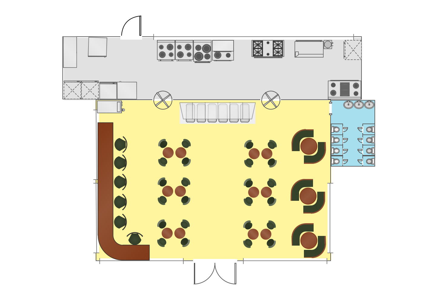
Restaurant Floor Plans Software

How To use Appliances Symbols for Building Plan

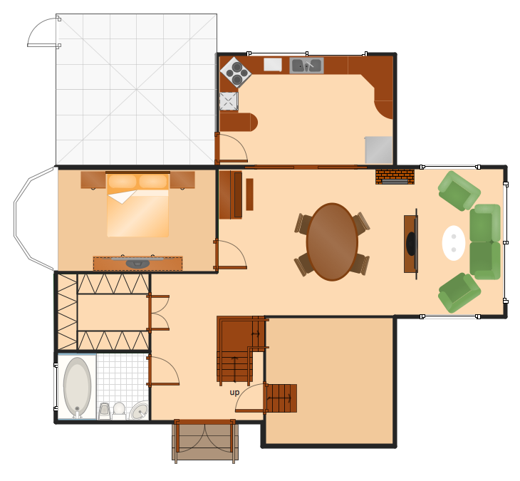
Make Your Own Floor Plans
How To Create Home Plan with Examples


 Floor Plans
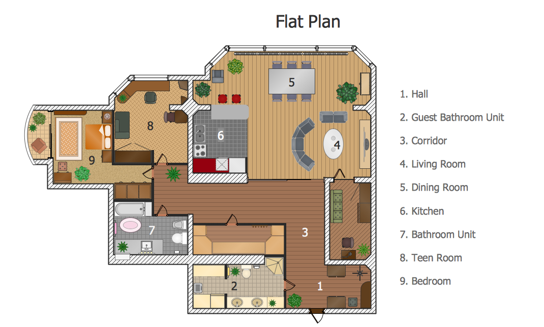
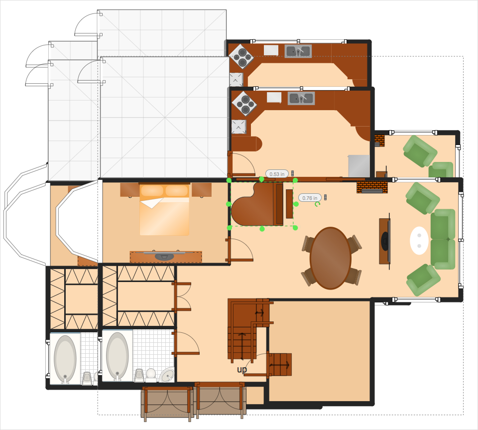
Construction, repair and remodeling of the home, flat, office, or any other building or premise begins with the development of detailed building plan and floor plans. Correct and quick visualization of the building ideas is important for further construction of any building.
This cafe electrical floor plan sample shows the outlet and switch layout.
"An electrical drawing, is a type of technical drawing that shows information about power, lighting, and communication for an engineering or architectural project. Any electrical working drawing consists of "lines, symbols, dimensions, and notations to accurately convey an engineering's design to the workers, who install the electrical system on the job".
A complete set of working drawings for the average electrical system in large projects usually consists of:
(1) A plot plan showing the building's location and outside electrical wiring.
(2) Floor plans showing the location of electrical systems on every floor.
(3) Power-riser diagrams showing panel boards.
(4) Control wiring diagrams.
(5) Schedules and other information in combination with construction drawings.
Electrical drafters prepare wiring and layout diagrams used by workers who erect, install, and repair electrical equipment and wiring in communication centers, power plants, electrical distribution systems, and buildings." [Electrical drawing. Wikipedia]
The outlet and switch layout example "Cafe electrical floor plan" was created using the ConceptDraw PRO diagramming and vector drawing software extended with the Electric and Telecom Plans solution from the Building Plans area of ConceptDraw Solution Park.
Outlet and switch layout

Interior Design
The vector stencils library "Electrical and telecom" contains 83 symbols of electrical and telecommunication equipment for electrical drawings and wiring diagrams of buildings, communication centers, power plants and electrical distribution systems.
"An electrical drawing, is a type of technical drawing that shows information about power, lighting, and communication for an engineering or architectural project." [Electrical drawing. Wikipedia]
Use the design elements library "Electrical and telecom" to design your own electrical drawings, plot plans of the building outside electrical wiring, floor plans with electrical and telecommunication systems layout, power-riser diagrams with panel boards, control wiring diagrams and cabling layout schemes, reflected ceiling plans and lighting panels layouts using the ConceptDraw PRO diagramming and vector drawing software.
The shapes library "Electrical and telecom" is included in the Electric and Telecom Plans solution from the Building Plans area of ConceptDraw Solution Park.
Electrical and telecom symbols

The vector stencils library "Video and audio" contains 50 symbols of audio and video devices and equipment.
Use the design elements library "Video and audio" for drawing audio and video system layouts, cabling floor plans, electrical circuit schematics and wiring diagrams of video and sound reproduction systems using the ConceptDraw PRO diagramming and vector drawing software.
Using the "Video and audio" library you can create video and audio engineering drawings and layout plans of your digital and analog, stereophonic (stereo), high fidelity (Hi-Fi, or hifi), quadraphonic, surround-sound, and home audio systems, home entertainment systems, home cinema (home theater, or home theatre), high-definition television (HDTV) and 3D television systems.
The shapes library "Video and audio" is included in the Electric and Telecom Plans solution from the Building Plans area of ConceptDraw Solution Park.
Video and audio symbols

How To Make a Floor Plan
The vector stenvils library "Outlets" contains 57 symbols of electrical outlets for drawing building interior design, electrical floor plans and layouts of AC power plugs and sockets.
"AC power plugs and sockets are devices that allow electrically operated equipment to be connected to the primary alternating current (AC) power supply in a building. Electrical plugs and sockets differ in voltage and current rating, shape, size and type of connectors. The types used in each country are set by national standards, some of which are listed in the IEC technical report TR 60083, Plugs and socket-outlets for domestic and similar general use standardized in member countries of IEC.
Plugs and sockets for portable appliances started becoming available in the 1880s, to replace connections to light sockets with easier to use wall-mounted outlets. A proliferation of types developed to address the issues of convenience and protection from electric shock. Today there are approximately 20 types in common use around the world, and many obsolete socket types are still found in older buildings. Co-ordination of technical standards has allowed some types of plugs to be used over wide regions to facilitate trade in electrical appliances, and for the convenience of travellers and consumers of imported electrical goods. Some multi-standard sockets allow use of several different types of plugs; improvised or unapproved adapters between incompatible sockets and plugs may not provide the full safety and performance of an approved adapter." [AC power plugs and sockets. Wikipedia]
The example "Design elements - Outlets" was created using the ConceptDraw PRO diagramming and vector drawing software extended with the Electric and Telecom Plans solution from the Building plans area of ConceptDraw Solution Park.
Electrical outlet symbols

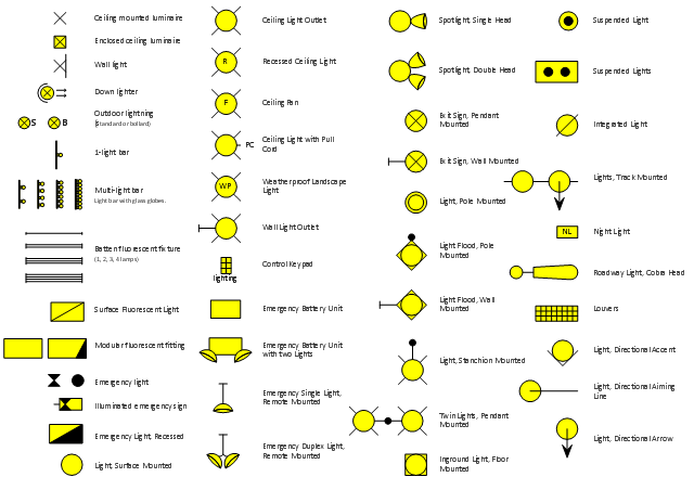
The vector stencils library "Lighting" contains 55 symbols of lighting devices and equipment.
Use these shapes for drawing lighting design floor plans, circuit schematic and wiring diagrams, cabling layouts, and reflected ceiling plans in the ConceptDraw PRO diagramming and vector drawing software.
The vector stencils library "Lighting" is included in the Electric and Telecom Plans solution from the Building Plans area of ConceptDraw Solution Park.
Luminaire ceiling mount

Enclosed ceiling luminaire

Wall light

Down lighter

Outdoor lightning

Outdoor lightning, bollard

1-light bar

2-light bar

4-light bar

6-light bar

8-light bar

Batten fluorescent, 1 lamp

Batten fluorescent, 2 lamps

Batten fluorescent, 3 lamps

Batten fluorescent, 4 lamps

Surface Fluorescent Light

Modular fluorescent fitting

Modular fluorescent fitting, inverter

Modular fluorescent fitting 2

Emergency light

Emergency light 2

Emergency sign

Emergency Light, Recessed

Light, Surface Mounted

Ceiling Light Outlet

Recessed Ceiling Light

Ceiling Fan

Ceiling Light with Pull Cord

Weatherproof Landscape Light

Wall Light Outlet

Control Keypad

Emergency Battery Unit

Emergency Battery Unit with two Lights

Emergency Single Light, Remote Mounted

Emergency Duplex Light, Remote Mounted

Spotlight, Single Head

Spotlight, Double Head

Exit Sign, Pendant Mounted

Exit Sign, Wall Mounted

Light, Pole Mounted

Light Flood, Pole Mounted

Light Flood, Wall Mounted

Light, Stanchion Mounted

Twin Lights, Pendant Mounted

Inground Light, Floor Mounted

Suspended Light

Suspended Lights

Integrated Light

Lights, Track Mounted

Night Light

Roadway Light, Cobra Head

Louvers

Light, Directional Accent

Light, Directional Aiming Line

Light, Directional Arrow
The vector stencils library "Lighting" contains 55 symbols of lighting devices and equipment, light sources, lamps and light fixtures.
"Lighting or illumination is the deliberate use of light to achieve a practical or aesthetic effect. Lighting includes the use of both artificial light sources like lamps and light fixtures, as well as natural illumination by capturing daylight.
Indoor lighting is usually accomplished using light fixtures, and is a key part of interior design. Lighting can also be an intrinsic component of landscape projects." [Lighting. Wikipedia]
Use the design elements library "Lighting" for drawing lighting design floor plans, circuit schematic and wiring diagrams, cabling layouts, and reflected ceiling plans using the ConceptDraw PRO diagramming and vector drawing software.
The shapes library "Lighting" is included in the Electric and Telecom Plans solution from the Building Plans area of ConceptDraw Solution Park.
Lighting symbols
Create a Floor Plan
Interior Design. Storage and Distribution — Design Elements

HelpDesk
How to Resize Objects
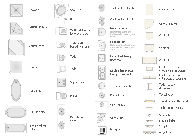
The vector stencils library Bathroom contains 41 symbols of bathtubs, toilets, faucets, sinks, showers, bathroom furniture.
Use the shapes library Bathroom to draw the bathroom furniture and equipment layouts and bathroom interioir plans using the ConceptDraw PRO diagramming and vector drawing software.
"A bathroom is a room for personal hygiene, generally containing a bathtub or a shower, and possibly also a bidet. In North America and some other regions, it characteristically contains a toilet and a sink...
Variations: Powder room, Shower room, Ensuite, Family bathroom, Jack and Jill bathroom, Wetroom." [Bathroom. Wikipedia]
The design elements library Bathroom is provided by the Floor Plans solution from Building Plans area of ConceptDraw Solution Park.
- Design elements - Doors and windows | Restaurant Floor Plans ...
- Wall Symbols For Floor Plan
- Design elements - Network layout floorplan | Design elements ...
- Network Layout Floor Plans | Network Layout | Design elements ...
- Design elements - Walls , shell and structure | Divider Floor Plan ...
- Network Layout Floor Plans | Ethernet local area network layout floor ...
- Power socket outlet layout | Outlets - Vector stenvils library | Design ...
- Cafe Floor Plans | Building Plans with ConceptDraw PRO | Design ...
- Local network physical topology floor plan | ConceptDraw PRO ...
- Building Drawing Software for Design Office Layout Plan | Cisco ...
- Lighting and switch layout | Design elements - Electrical and telecom
- Bookcase Symbols
- Basic Flowchart Symbols and Meaning | Chemistry Symbols and ...
- How To Draw Building Plans | Cafe Floor Plans | Building Drawing ...
- Create Floor Plans easily with ConceptDraw PRO! | How To Create ...
- Design elements - Appliances | Network layout floorplan - Vector ...
- Design elements - Network layout floorplan | How To Create ...
- Design elements - Network layout floorplan | Network layout ...
- Design elements - Network layout floorplan | Network layout ...
- Architectural Symbols For Doors And Windows