This site uses cookies. By continuing to browse the ConceptDraw site you are agreeing to our Use of Site Cookies.

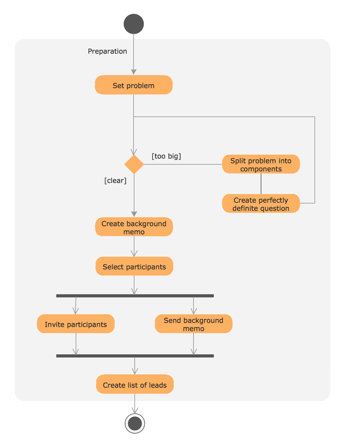
UML Process Diagram Example

This sample shows the UML Activity Diagram that describes the flow of controls in the system. This is preparation to see how the system will work when executed. Black circle indicates the start of the workflow, encircled black circle indicates the end of the workflow. This sample shows the decision of the problem and can be used when you need to solve some set of problems.

Entity Relationship Diagram Symbols

Creating an entity-relationship (ER) model is to visually represent the structure of a business database, where data equates to entities (or objects) that are linked by defined relationships expressing dependencies and requirements. By nature it is an abstract visualization, the first step in the design process towards creating a logical and functional database.
ERD symbols used for professional ERD drawing are collected in libraries from the Entity-Relationship Diagram (ERD) solution for ConceptDraw DIAGRAM.

Data Flow Diagram

Data flow diagram (DFD) is the part of the SSADM method (Structured Systems Analysis and Design Methodology), intended for analysis and information systems projection. Data flow diagrams are intended for graphical representation of data flows in the information system and for analysis of data processing during the structural projection. Data flow diagram often used in connection with human process and can be displayed as workflow diagram. The critical Process Flow Diagram is another flowchart technique for designing data flow in connection with organizational processes. The critical Process flow diagram may use different range of symbols than a classic workflow diagram.

floor plan sample Floor Plans

floor plan sample
Construction, repair and remodeling of the home, flat, office, or any other building or premise begins with the development of detailed building plan and floor plans. Correct and quick visualization of the building ideas is important for further construction of any building.

Diagramming Software for Design UML Collaboration Diagrams

ConceptDraw helps you to start designing your own UML Collaboration Diagrams with examples and templates.

Network Topologies

Running your own business or working for some company as IT specialist, one day you definitely face the need of connecting all network and computer devices existing on this enterprise's balance sheet. Especially once this company grows you need more stuff and so elements of network such as laptops, servers, scanners, printers, fax machines, telephones, routers, so you definitely have to make network topology flowchart to arrange it all correctly to connect it with each other. In this case to use ConceptDraw DIAGRAM as a tool to make your topology diagram is the best decision ever! Test how simple it is to use our samples to create your diagrams in a short term! Whether you need to make logical or physical topologies you can always use the service of our software and with help of libraries to design whatever you need. The basic topologies types are: ring, mesh, bus, star, tree or fully connected one, and its examples are there in Solutions waiting for you on this site to use it all. Check it out and enjoy simplicity of using this application right now!
Create Network Topology Diagram

workflow diagram software, workflow patterns Workflow Diagrams

workflow diagram software, workflow patterns
Workflow Diagrams solution extends ConceptDraw DIAGRAM software with samples, templates and vector stencils library for drawing the work process flowcharts.

UML Sequence Diagram. Design Elements

UML Sequence Diagram shows object interactions arranged in time sequence, how processes operate with one another and in what order and illustrate the sequence of messages exchanged between the objects and classes involved in the scenario.

Cloud Computing Architecture Diagrams

For documenting the Cloud Computing Architecture with a goal to facilitate the communication between stakeholders are successfully used the Cloud Computing Architecture diagrams. It is convenient and easy to draw various Cloud Computing Architecture diagrams in ConceptDraw DIAGRAM software with help of tools of the Cloud Computing Diagrams Solution from the Computer and Networks Area of ConceptDraw Solution Park.

IDEF4 Standard

Use Case Diagrams technology. IDEF4 standard implies not only graphical presentation but the additional information about diagrams of heredity, methods systematization and types which are contained in specifications.