How To use House Electrical Plan Software


Electrical Symbols, Electrical Diagram Symbols

 Electric and Telecom Plans
The Electric and Telecom Plans solution providing the electric and telecom-related stencils, floor plan electrical symbols and pre-made examples is useful for electricians, interior designers, telecommunications managers, builders and other technicians when creating the electric visual plans and telecom drawings, home electrical plan, residential electric plan, telecom wireless plan, electrical floor plans whether as a part of the building plans or the independent ones.
Network wiring cable. Computer and Network Examples


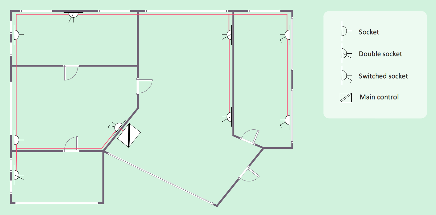
Residential Electric Plan
Electrical and Telecom Plan Software

Electrical Drawing Software and Electrical Symbols

Home Electrical Plan

Electrical Symbols — Resistors

CAD Drawing Software for Making Mechanic Diagram and Electrical Diagram Architectural Designs

- Floor Plan Electrical Layout Image With Details
- Examples For Schematic Diagram For Residential Building
- How To use House Electrical Plan Software | Interior Design ...
- Classroom lighting - Reflected ceiling plan | Reflected ceiling plan ...
- How To use House Electrical Plan Software | Residential Electric ...
- Electrical Symbols, Electrical Diagram Symbols | Home Electrical ...
- Cafe electrical floor plan | Restaurant Floor Plans Samples | How To ...
- Electrical Symbols, Electrical Diagram Symbols | How To use House ...
- How To use House Electrical Plan Software | Electrical Drawing ...
- Electrical Engineering | Design elements - Kitchen and dining room ...