Star Network Topology


The vector stencils library "Composite assemblies" contains 44 element symbols of transmitters (electronic amplifiers, repeaters), static devices (rectifiers), phase shift circuits, gyroscopes, and gyrators.
Use it to design the electronic circuit diagrams and electrical schematics in the ConceptDraw PRO diagramming and vector drawing software extended with the Electrical Engineering solution from the Engineering area of ConceptDraw Solution Park.
www.conceptdraw.com/ solution-park/ engineering-electrical
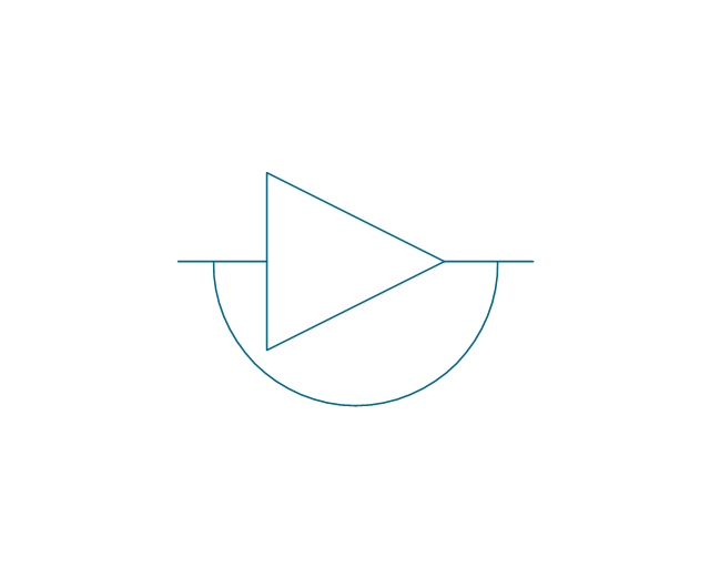
Amplifier with bypass
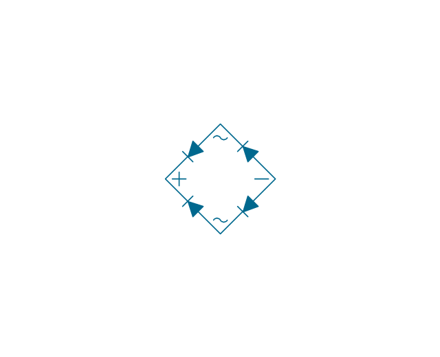
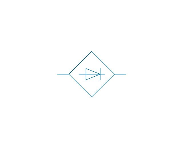
Bridge rectifier
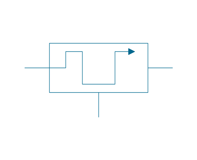
Chopper
Demodulator
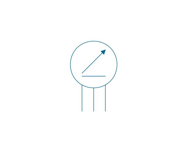
Gyro

Position indicator synchro
Position indicator inductor
Position transmitter Desynn
Position transmitter inductor
Fire ext. actuator
Fire ext. double
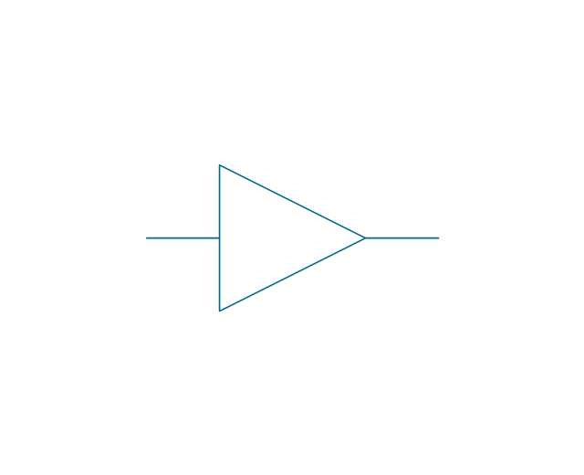
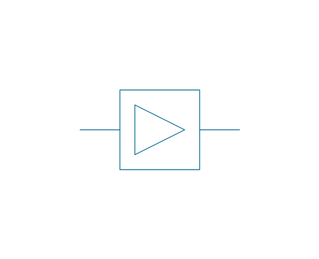
Amplifier, 1 line
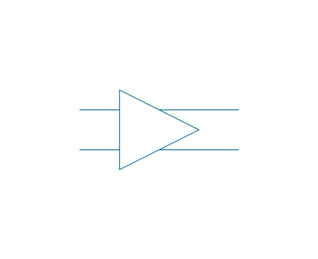
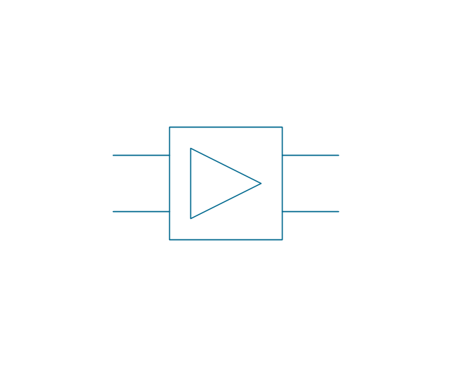
Amplifier, 2 lines
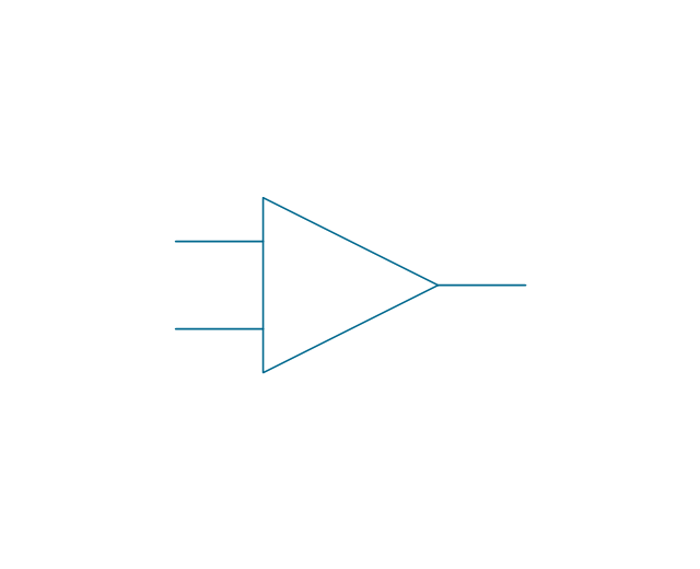
Amplifier, 2 inputs
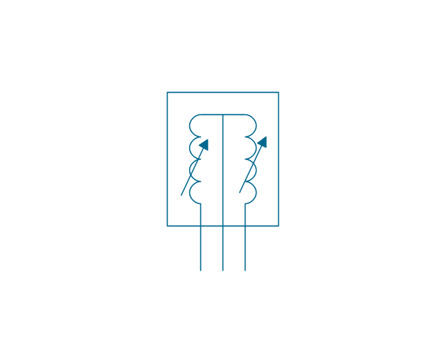
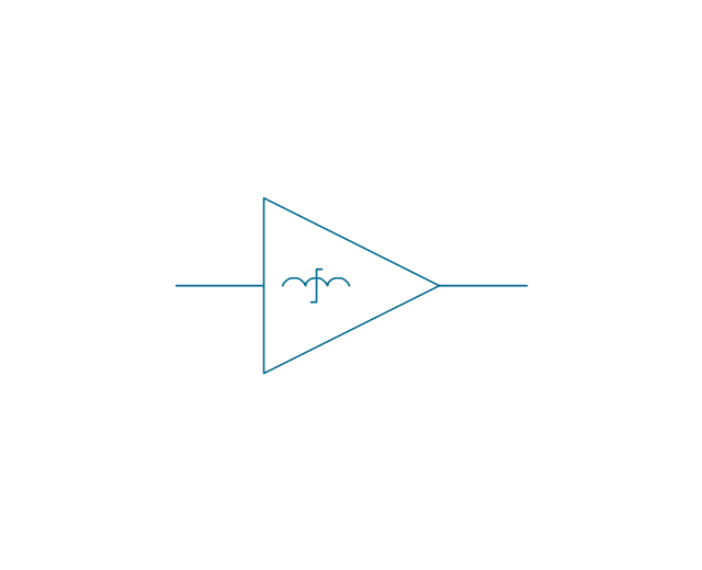
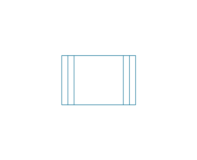
Magnetic amplifier, 1 line
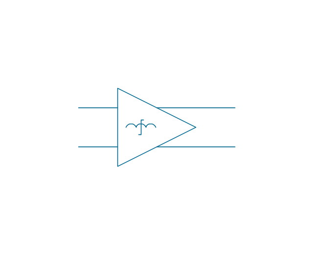
Magnetic amplifier, 2 lines
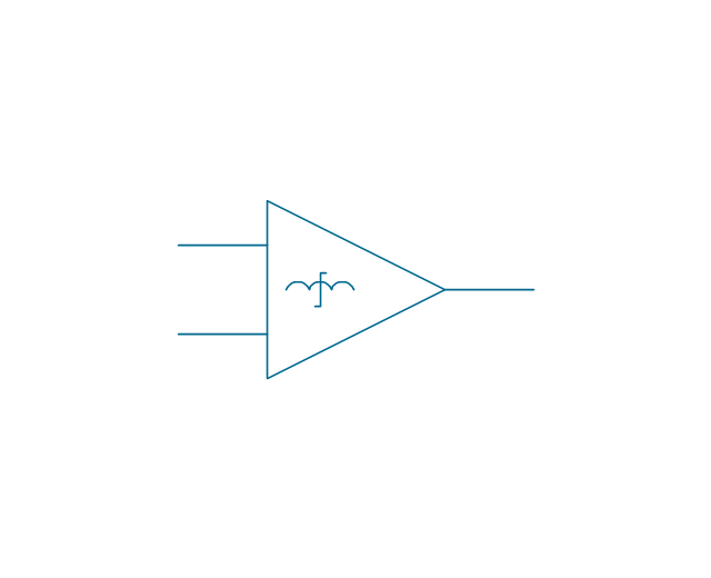
Magnetic amplifier, 2 inputs
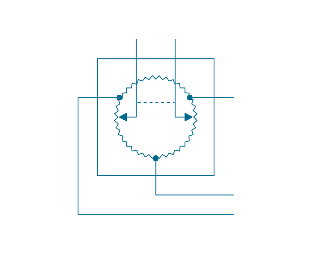
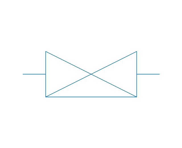
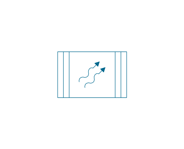
Negative impedance both-way amplifier
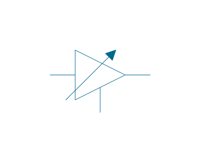
Amplifier external DC control
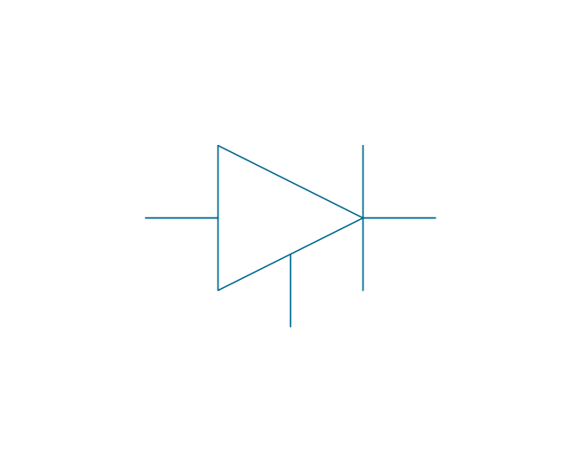
Controlled rectifier
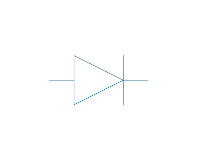
Rectifier
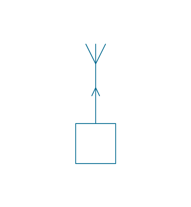
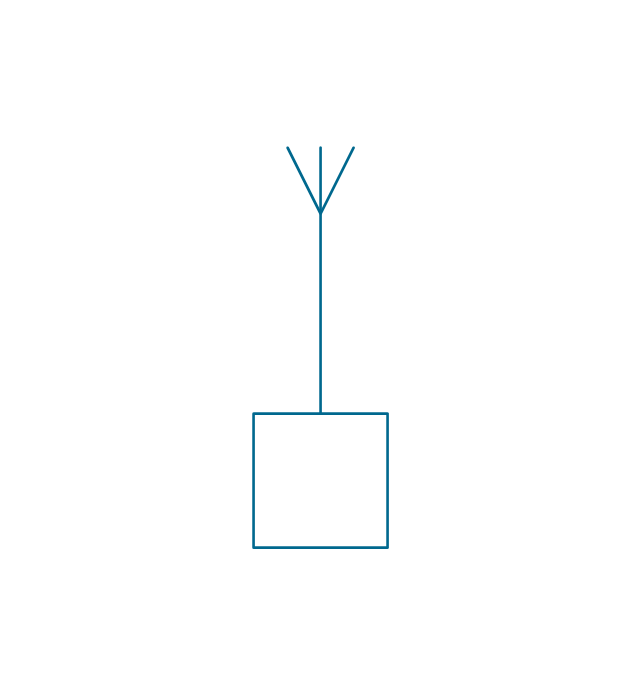
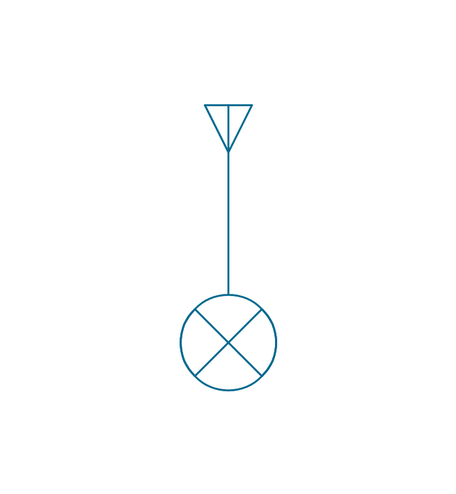
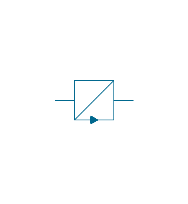
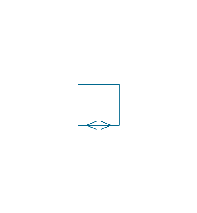
1-way repeater, 1 line
1-way repeater, 2 lines
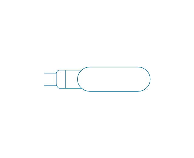
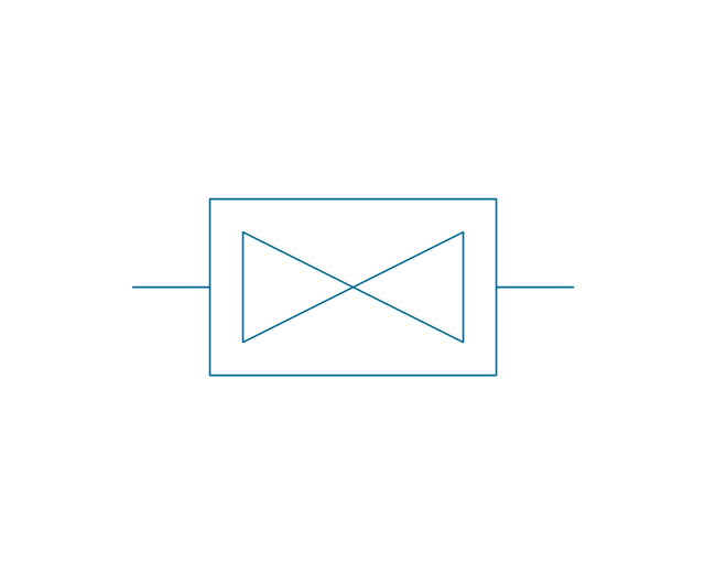
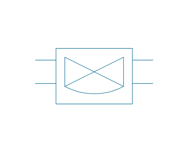
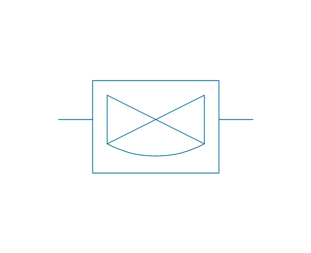
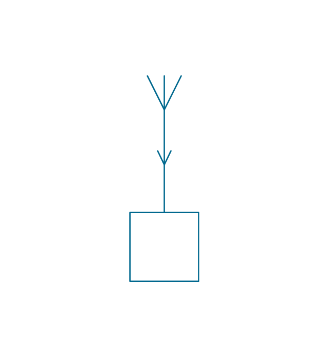
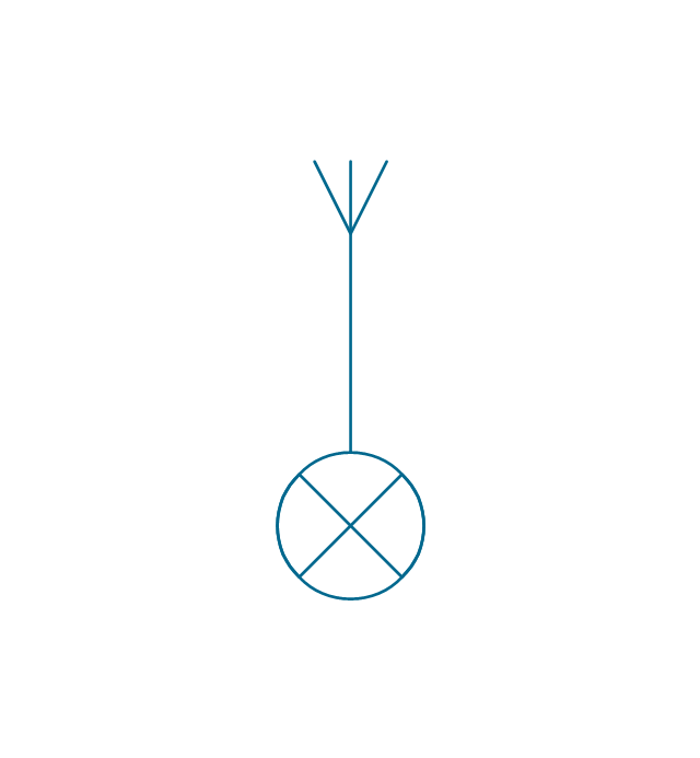
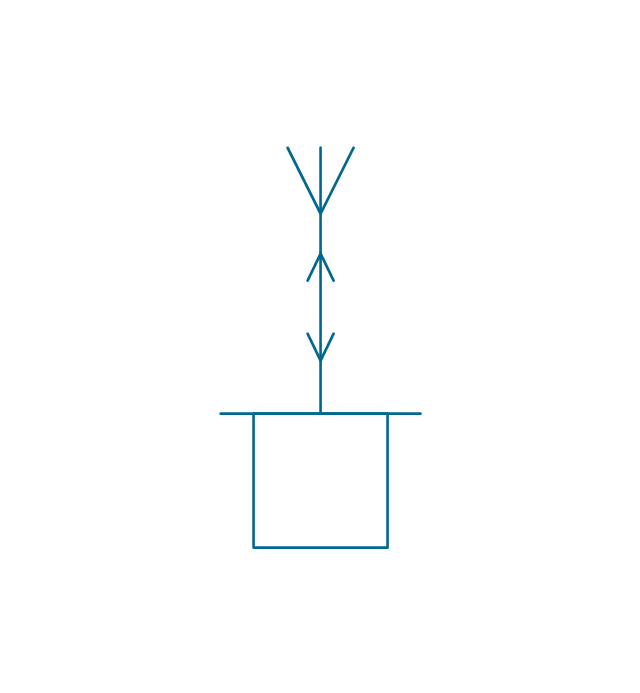
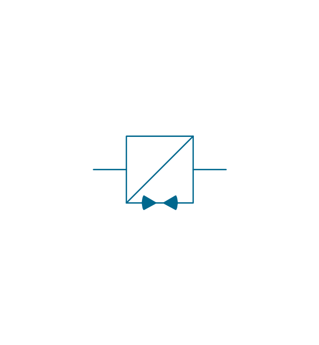
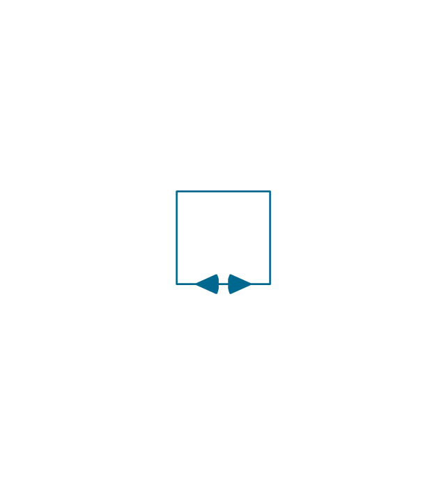
2-way repeater, 1 line
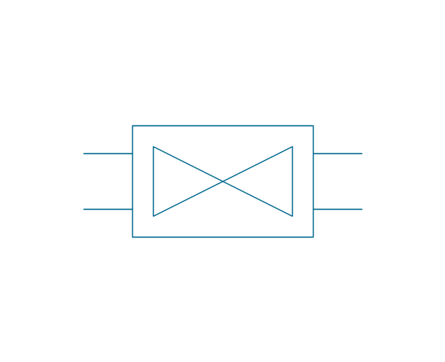
2-way repeater, 2 lines
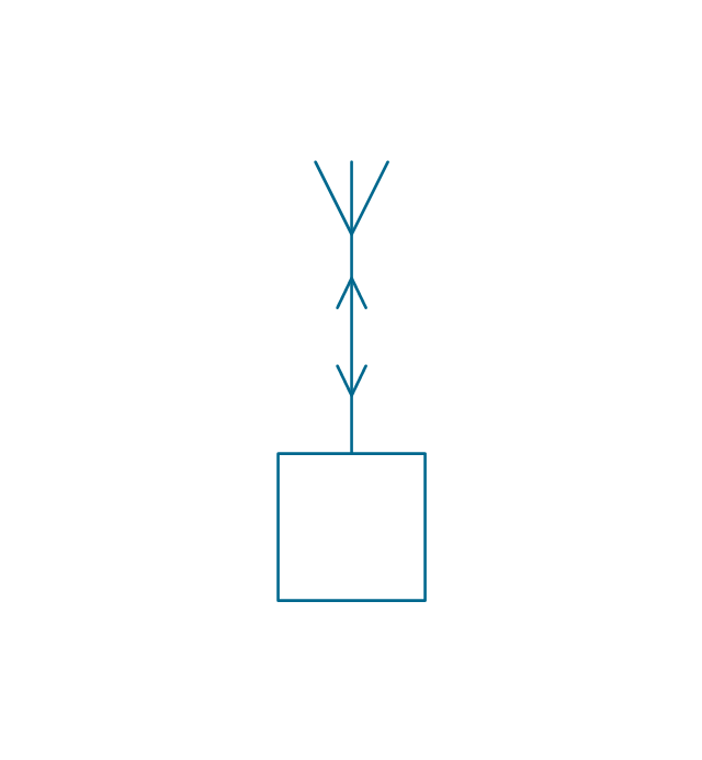
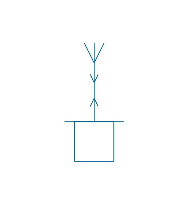
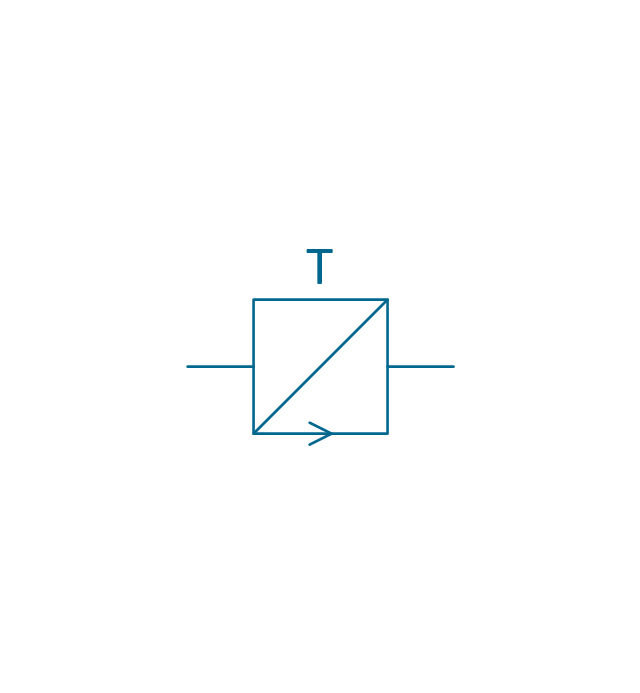
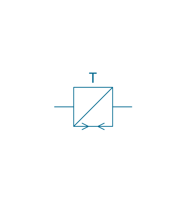
2-way repeater, bypass, 2 lines
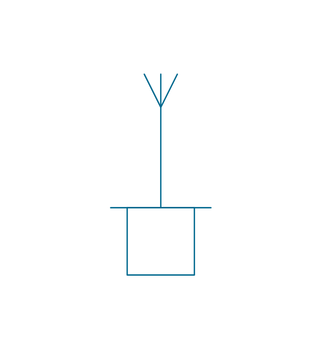
2-way repeater, bypass, 1 line
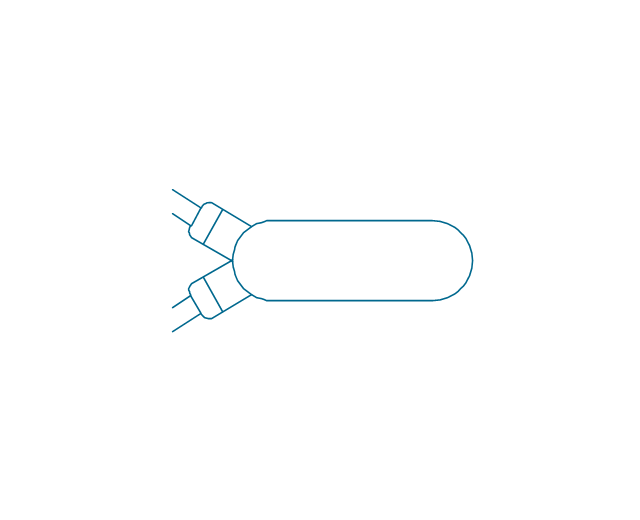
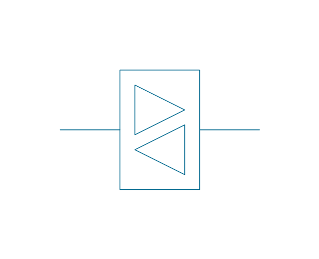
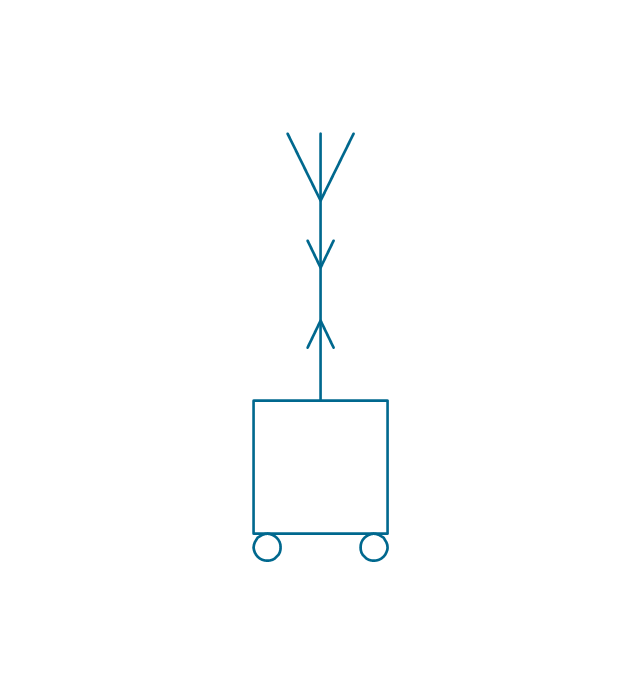
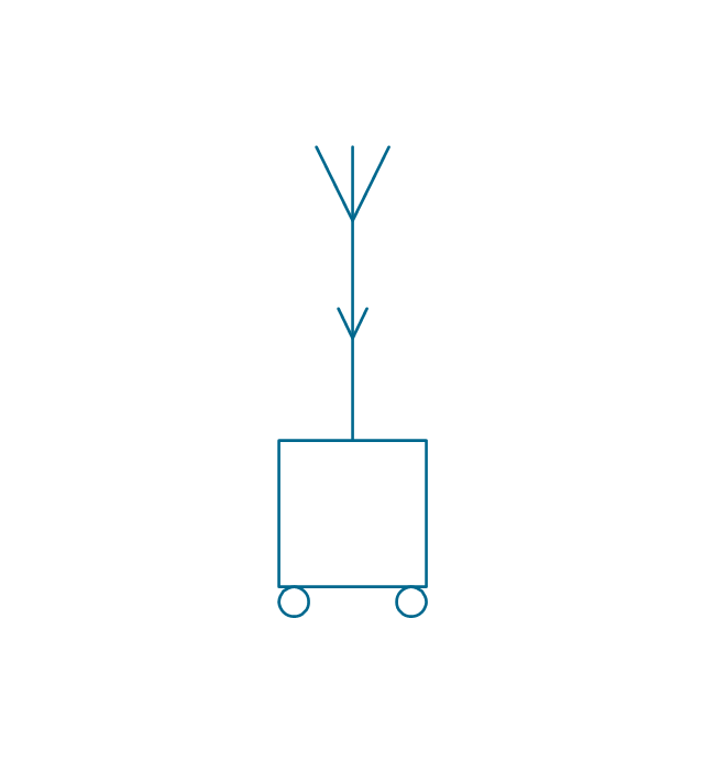
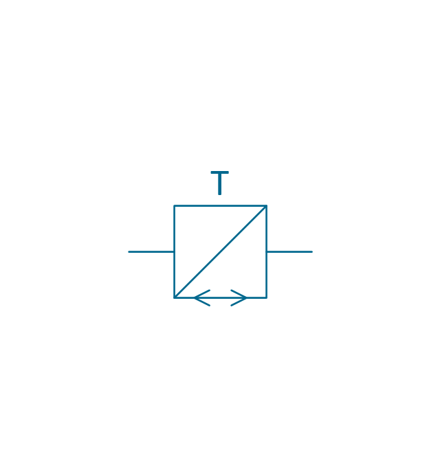
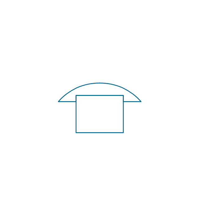
2-way repeater, 4-wire, 4 lines
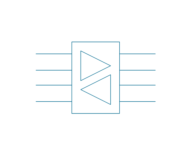
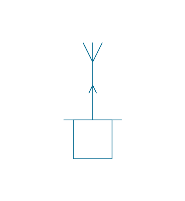
2-way repeater, 4-wire, 1 line
Network low voltage
Phase shifter, general
Phase shifter, 3-wire
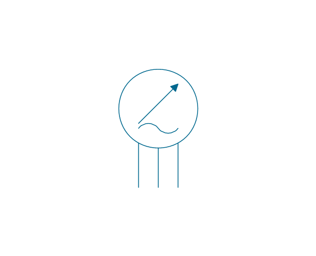
Gyro 2
Converter, general
DC converter
Rectifier
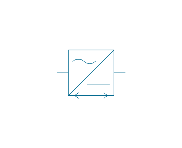
Inverter
Rectifier/inverter
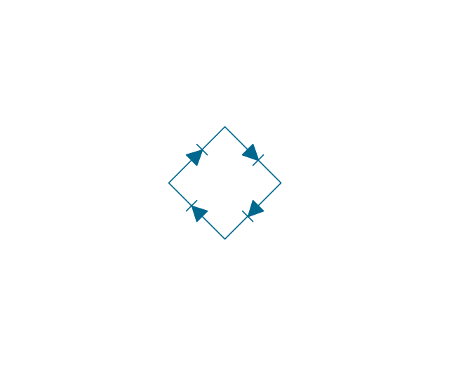
Rectifier bridge
Heat source, general
Heat source, radioisotope
Heat source, combustion
Proximity sensor
Touch sensor

The vector stencils library "Composite assemblies" contains 44 element symbols of transmitters (electronic amplifiers, repeaters), static devices (rectifiers), phase shift circuits, gyroscopes, and gyrators.
Use it to design the electronic circuit diagrams and electrical schematics in the ConceptDraw PRO diagramming and vector drawing software extended with the Electrical Engineering solution from the Engineering area of ConceptDraw Solution Park.
www.conceptdraw.com/ solution-park/ engineering-electrical
Use it to design the electronic circuit diagrams and electrical schematics in the ConceptDraw PRO diagramming and vector drawing software extended with the Electrical Engineering solution from the Engineering area of ConceptDraw Solution Park.
www.conceptdraw.com/ solution-park/ engineering-electrical
Amplifier with bypass
Bridge rectifier
Chopper
Demodulator
Gyro
Position indicator synchro
Position indicator inductor
Position transmitter Desynn
Position transmitter inductor
Fire ext. actuator
Fire ext. double
Amplifier, 1 line
Amplifier, 2 lines
Amplifier, 2 inputs
Magnetic amplifier, 1 line
Magnetic amplifier, 2 lines
Magnetic amplifier, 2 inputs
Negative impedance both-way amplifier
Amplifier external DC control
Controlled rectifier
Rectifier
1-way repeater, 1 line
1-way repeater, 2 lines
2-way repeater, 1 line
2-way repeater, 2 lines
2-way repeater, bypass, 2 lines
2-way repeater, bypass, 1 line
2-way repeater, 4-wire, 4 lines
2-way repeater, 4-wire, 1 line
Network low voltage
Phase shifter, general
Phase shifter, 3-wire
Gyro 2
Converter, general
DC converter
Rectifier
Inverter
Rectifier/inverter
Rectifier bridge
Heat source, general
Heat source, radioisotope
Heat source, combustion
Proximity sensor
Touch sensor
The vector stencils library "Vertex" contains 9 clipart icons of Vertex devices for drawing computer network diagrams and telecommunication equipment layouts.
"Vertex Standard is exclusively focused in offering a broad portfolio of analogue and digital two-way radios...
Products: Portable Radios, Mobile Radios, Repeaters / Base Stations, HF SSB Radios, APCO P25 Radios, Digital TDMA Radios (DMR), Trunking Radios." [vertex-standard-emea.com]
The clip art example "Vertex - Vector stencils library" was created using the ConceptDraw PRO diagramming and vector drawing software extended with the Telecommunication Network Diagrams solution from the Computer and Networks area of ConceptDraw Solution Park.
www.conceptdraw.com/ solution-park/ computer-networks-telecommunication
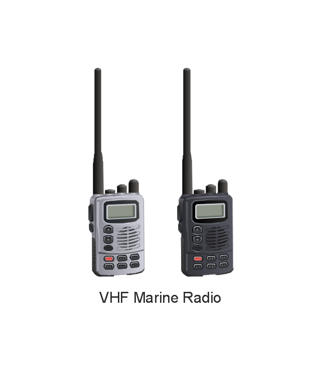
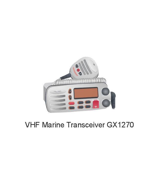
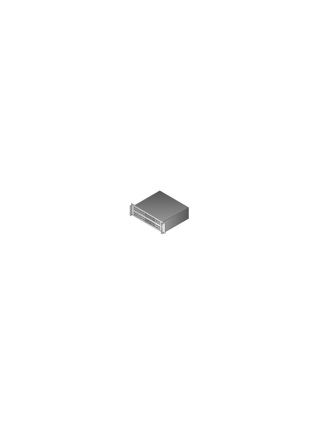
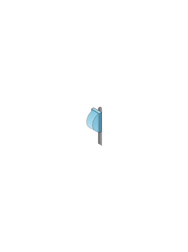
VHF Marine Radio
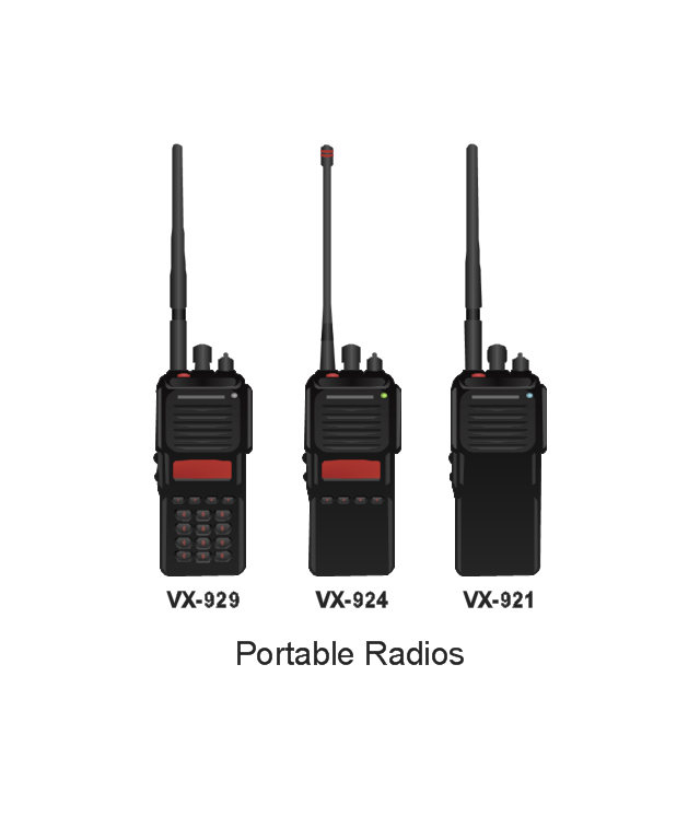
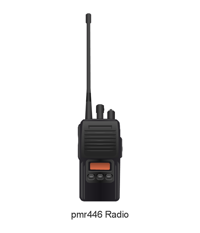
Portable Radios
pmr446 Radio
VHF Marine Transceiver GX1270
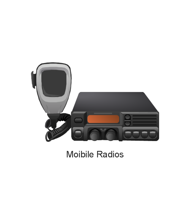
Moibile Radios
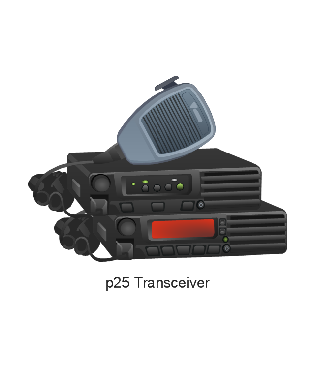
p25 Transceiver
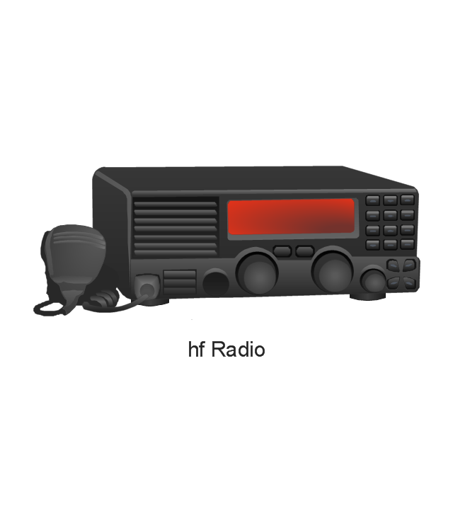
hf Radio
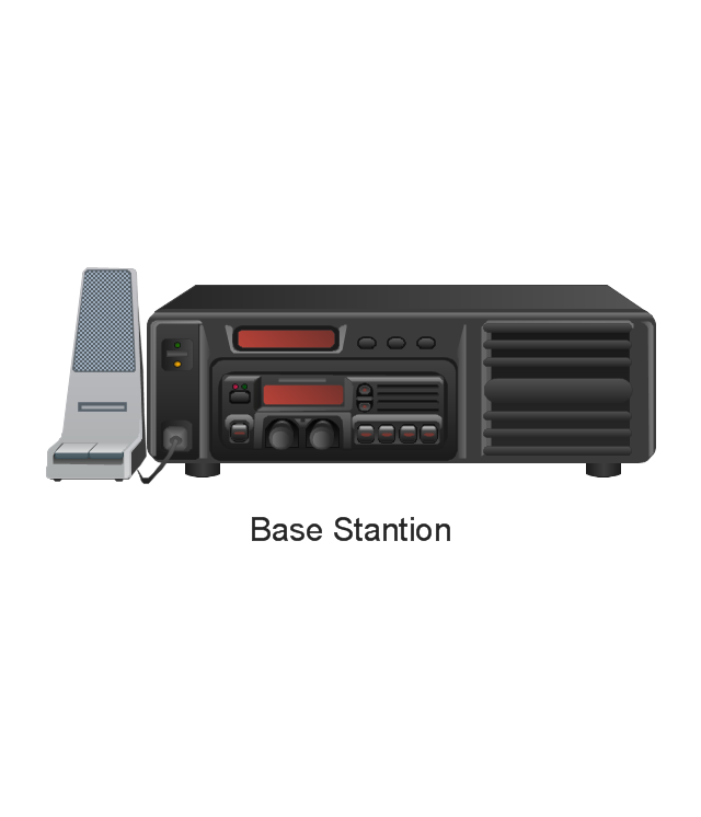
Base Stantion
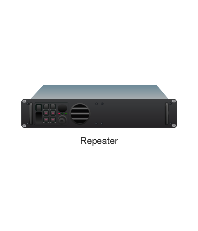
Repeater
The vector stencils library "Cisco LAN" contains 23 symbols of local area network (LAN) devices and equipment for drawing Cisco LAN topology diagrams.
"Network topology describes the layout of interconnections between devices and network segments. At the Data Link Layer and Physical Layer, a wide variety of LAN topologies have been used, including ring, bus, mesh and star, but the most common LAN topology in use today is switched Ethernet. At the higher layers, the Internet Protocol (TCP/ IP) has become the standard, replacing NetBEUI, IPX/ SPX, AppleTalk and others.
Simple LANs generally consist of one or more switches. A switch can be connected to a router, cable modem, or ADSL modem for Internet access. Complex LANs are characterized by their use of redundant links with switches using the spanning tree protocol to prevent loops, their ability to manage differing traffic types via quality of service (QoS), and to segregate traffic with VLANs. A LAN can include a wide variety of network devices such as switches, firewalls, routers, load balancers, and sensors.
LANs can maintain connections with other LANs via leased lines, leased services, or the Internet using virtual private network technologies. Depending on how the connections are established and secured in a LAN, and the distance involved, a LAN may also be classified as a metropolitan area network (MAN) or a wide area network (WAN)." [Local area network. Wikipedia]
The symbols example "Cisco LAN - Vector stencils library" was created using the ConceptDraw PRO diagramming and vector drawing software extended with the Cisco Network Diagrams solution from the Computer and Networks area of ConceptDraw Solution Park.
www.conceptdraw.com/ solution-park/ computer-networks-cisco
Sun workstation

Workstation

PC

Macintosh

Terminal

Mini VAX

Printer

Laptop

File server

Monitor

Web cluster

ATM fast gigabit etherswitch

HP Mini

Supercomputer

LAN2LAN

LAN to LAN

Web server

Web browser

Repeater

PDA

General appliance

PC, blue

Mini VAX, blue

The vector stencils library "Stations" contains 110 symbols of communications equipment, generating, transmitting and receiving stations; substations; satellites; and power plants.
Use these shapes for drawing diagrams of power generation and distribution and radio relay systems in the ConceptDraw PRO diagramming and vector drawing software extended with the Electrical Engineering solution from the Engineering area of ConceptDraw Solution Park.
www.conceptdraw.com/ solution-park/ engineering-electrical
Radio relay station
Transmission radio station
Radio station
Reception radio station
Alternating radio station
Simultaneous radio station
End radio station
End radio station 2

General radio station
General radio station 2
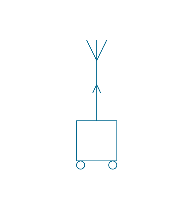
Repeater radio station
Repeater radio station 2
Portable station
Transmission portable station
Reception portable station

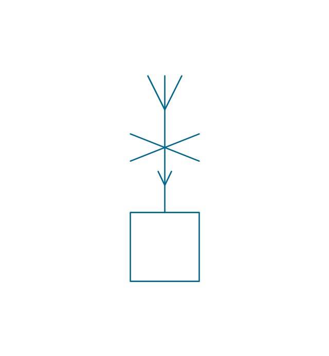
Alternating portable station
Simultaneous portable station
Mobile simultaneous station
Mobile alternating station

Mobile reception station
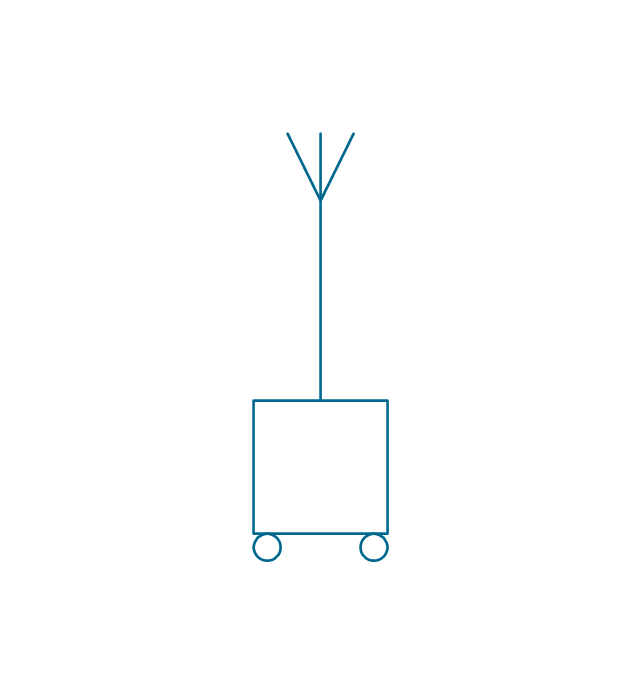
Mobile transmission station
Mobile station
Direction finding station
Radio beacon station
Simultaneous controlling station
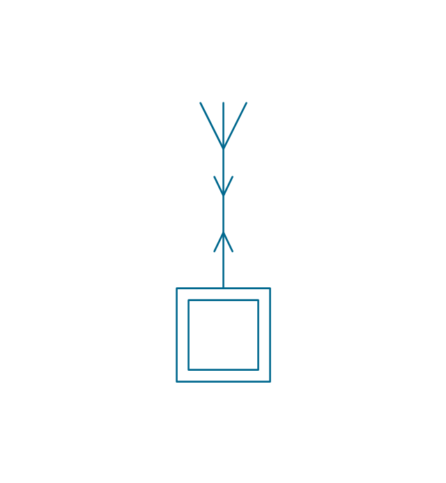
Alternating controlling station
Reception controlling station
Transmission controlling station
Controlling station
End station

Repeater station

Subscriber equipment
Subscriber equipment 2

Passive relay
Active space station

Passive space station
Space station

Earth tracking station
Earth communication service
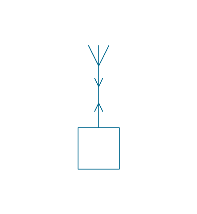
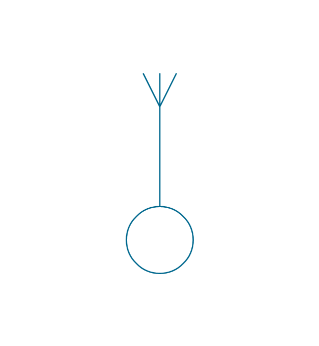
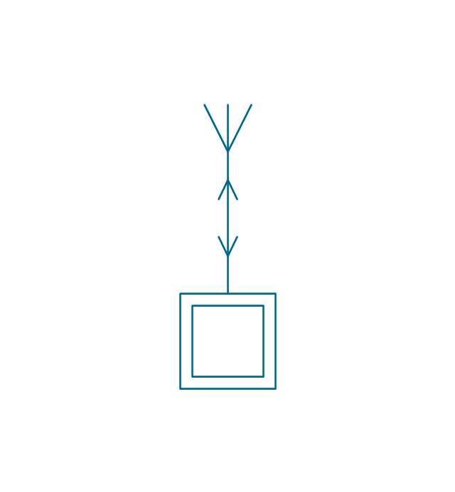
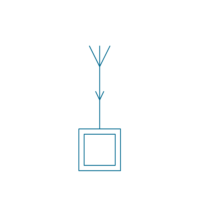
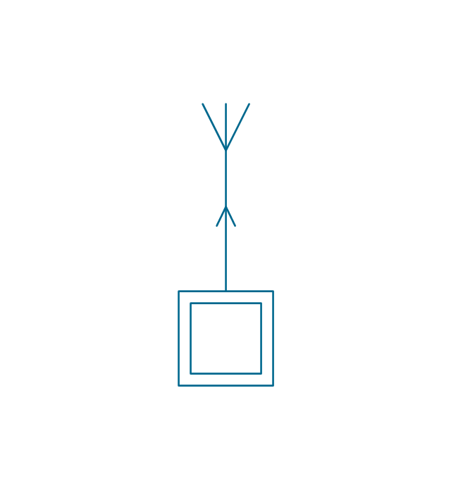
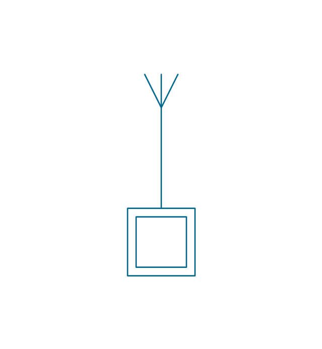
Telegraph repeater, one-way simplex
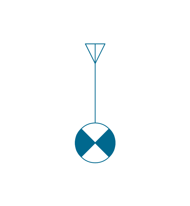
Telegraph repeater, two-way simplex

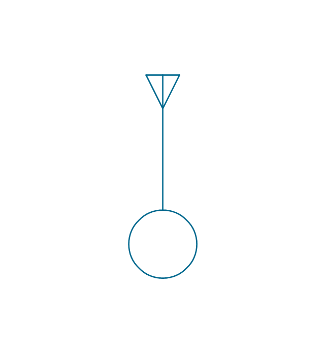
Telegraph repeater, duplex
Telegraph repeater, one-way simplex 2
Telegraph repeater, two-way simplex 2
Telegraph repeater, duplex 2
Telegraph repeater qualifiers, polar direct-current (double current)
-stations---vector-stencils-library.png--diagram-flowchart-example.png)
Telegraph repeater qualifier, neutral direct-current (single current) +/o
-+/o-stations---vector-stencils-library.png--diagram-flowchart-example.png)
Telegraph repeater qualifier, neutral direct-current (single current) -/o
--/o-stations---vector-stencils-library.png--diagram-flowchart-example.png)
Telegraph equipment

Telegraph transmitter

Telegraph receiver

Two-way simplex telegraph
Duplex telegraph

Telegraph transmitter 2

Telegraph receiver 2

Two-way simplex telegraph 2
Duplex telegraph 2

Telegraph equipment qualifier, tape printing

Telegraph equipment qualifier, tape perforating

Telegraph equipment qualifier, tape printing/perforating

Telegraph equipment qualifier, page printing

Telegraph equipment qualifier, keyboard

Telegraph equipment qualifier, facsimile

Telephone
Dial telephone

Push-button telephone

Multiple lines telephone
Coin box telephone
Speaker phone

Amplified phone

Generating station (in service)
-stations---vector-stencils-library.png--diagram-flowchart-example.png)
Generating station (planned)
-stations---vector-stencils-library.png--diagram-flowchart-example.png)
Electric heat station (in service)
-stations---vector-stencils-library.png--diagram-flowchart-example.png)
Electric heat station (planned)
-stations---vector-stencils-library.png--diagram-flowchart-example.png)
Hydroelectric station (planned)
-stations---vector-stencils-library.png--diagram-flowchart-example.png)
Hydroelectric station (in service)
-stations---vector-stencils-library.png--diagram-flowchart-example.png)
Hydroelectric station (planned) 2
-2-stations---vector-stencils-library.png--diagram-flowchart-example.png)
Hydroelectric station (in service) 2
-2-stations---vector-stencils-library.png--diagram-flowchart-example.png)
Hydroelectric station (planned) 3
-3-stations---vector-stencils-library.png--diagram-flowchart-example.png)
Hydroelectric station (in service) 3
-3-stations---vector-stencils-library.png--diagram-flowchart-example.png)
Hydroelectric station (planned) 4
-4-stations---vector-stencils-library.png--diagram-flowchart-example.png)
Hydroelectric station (in service) 4
-4-stations---vector-stencils-library.png--diagram-flowchart-example.png)
Thermoelectric station (planned)
-stations---vector-stencils-library.png--diagram-flowchart-example.png)
Thermoelectric station (in service)
-stations---vector-stencils-library.png--diagram-flowchart-example.png)
Coal fueled station (planned)
-stations---vector-stencils-library.png--diagram-flowchart-example.png)
Coal fueled station (in service)
-stations---vector-stencils-library.png--diagram-flowchart-example.png)
Oil/gas fueled station (planned)
-stations---vector-stencils-library.png--diagram-flowchart-example.png)
Oil/gas fueled station (in service)
-stations---vector-stencils-library.png--diagram-flowchart-example.png)
Nuclear station (planned)
-stations---vector-stencils-library.png--diagram-flowchart-example.png)
Nuclear station (in service)
-stations---vector-stencils-library.png--diagram-flowchart-example.png)
Geothermic station (planned)
-stations---vector-stencils-library.png--diagram-flowchart-example.png)
Geothermic station (in service)
-stations---vector-stencils-library.png--diagram-flowchart-example.png)
Solar station (planned)
-stations---vector-stencils-library.png--diagram-flowchart-example.png)
Solar station (in service)
-stations---vector-stencils-library.png--diagram-flowchart-example.png)
Wind station (planned)
-stations---vector-stencils-library.png--diagram-flowchart-example.png)
Wind station (in service)
-stations---vector-stencils-library.png--diagram-flowchart-example.png)
Converting substation (in service)
-stations---vector-stencils-library.png--diagram-flowchart-example.png)
Converting substation (planned)
-stations---vector-stencils-library.png--diagram-flowchart-example.png)
Substation (planned)
-stations---vector-stencils-library.png--diagram-flowchart-example.png)
Substation (in service)
-stations---vector-stencils-library.png--diagram-flowchart-example.png)
Prime mover, reciprocating engine

Prime mover, gas turbine

Converting station

Converting station 2

Switching station

Switching station 2

Rectifier substation (planned)
-stations---vector-stencils-library.png--diagram-flowchart-example.png)
Rectifier substation (in service)
-stations---vector-stencils-library.png--diagram-flowchart-example.png)
Plasma station MHD (planned)
-stations---vector-stencils-library.png--diagram-flowchart-example.png)
Plasma station MHD (in service)
-stations---vector-stencils-library.png--diagram-flowchart-example.png)
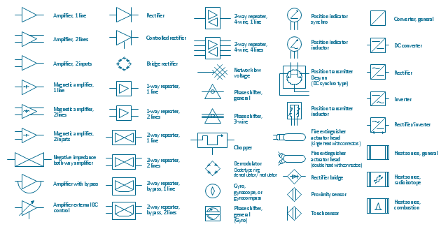
This vector stencils library contains 44 element symbols of transmitters (electronic amplifiers, repeaters), static devices (rectifiers), phase shift circuits, gyroscopes, and gyrators.
Use it to design the electronic circuit diagrams and electrical schematics.
"An electronic amplifier, amplifier, or (informally) amp is an electronic device that increases the power of a signal. It does this by taking energy from a power supply and controlling the output to match the input signal shape but with a larger amplitude. In this sense, an amplifier modulates the output of the power supply.
There are four basic types of electronic amplifier: the voltage amplifier, the current amplifier, the transconductance amplifier, and the transresistance amplifier. A further distinction is whether the output is a linear or exponential representation of the input. Amplifiers can also be categorized by their physical placement in the signal chain." [Amplifier. Wikipedia]
"A rectifier is an electrical device that converts Alternating Current (AC), which periodically reverses direction, to Direct Current (DC), which flows in only one direction. The process is known as rectification. Physically, rectifiers take a number of forms, including vacuum tube diodes, mercury-arc valves, copper and selenium oxide rectifiers, semiconductor diodes, silicon-controlled rectifiers and other silicon-based semiconductor switches." [Rectifier. Wikipedia]
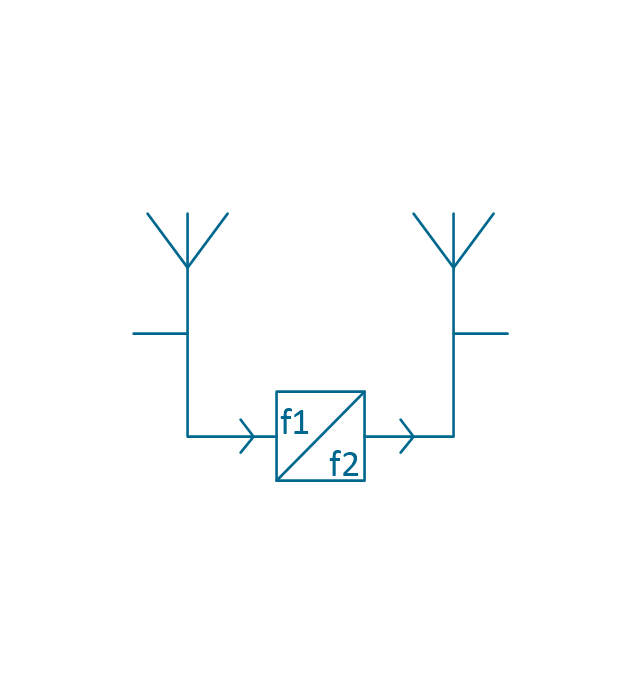
"In telecommunications, a repeater is an electronic device that receives a signal and retransmits it at a higher level or higher power, or onto the other side of an obstruction, so that the signal can cover longer distances." [Repeater. Wikipedia]
"A phase shifter is a microwave network which provides a controllable phase shift of the RF signal. Phase shifters are used in phased arrays." [Phase shift module. Wikipedia]
"A vibrating structure gyroscope, standardised by IEEE as Coriolis vibratory gyroscope (CVG), is a wide group of gyroscope using solid-state resonators of different shapes that functions much like the halteres of an insect.
The underlying physical principle is that a vibrating object tends to continue vibrating in the same plane as its support rotates. In the engineering literature, this type of device is also known as a Coriolis vibratory gyro because as the plane of oscillation is rotated, the response detected by the transducer results from the Coriolis term in its equations of motion ("Coriolis force").
Vibrating structure gyroscopes are simpler and cheaper than conventional rotating gyroscopes of similar accuracy. Miniature devices using this principle are a relatively inexpensive type of attitude indicator." [Vibrating structure gyroscope. Wikipedia]
The example "Design elements - Composite assemblies" was drawn using the ConceptDraw PRO diagramming and vector drawing software extended with the Electrical Engineering solution from the Engineering area of ConceptDraw Solution Park.
Use it to design the electronic circuit diagrams and electrical schematics.
"An electronic amplifier, amplifier, or (informally) amp is an electronic device that increases the power of a signal. It does this by taking energy from a power supply and controlling the output to match the input signal shape but with a larger amplitude. In this sense, an amplifier modulates the output of the power supply.
There are four basic types of electronic amplifier: the voltage amplifier, the current amplifier, the transconductance amplifier, and the transresistance amplifier. A further distinction is whether the output is a linear or exponential representation of the input. Amplifiers can also be categorized by their physical placement in the signal chain." [Amplifier. Wikipedia]
"A rectifier is an electrical device that converts Alternating Current (AC), which periodically reverses direction, to Direct Current (DC), which flows in only one direction. The process is known as rectification. Physically, rectifiers take a number of forms, including vacuum tube diodes, mercury-arc valves, copper and selenium oxide rectifiers, semiconductor diodes, silicon-controlled rectifiers and other silicon-based semiconductor switches." [Rectifier. Wikipedia]
"In telecommunications, a repeater is an electronic device that receives a signal and retransmits it at a higher level or higher power, or onto the other side of an obstruction, so that the signal can cover longer distances." [Repeater. Wikipedia]
"A phase shifter is a microwave network which provides a controllable phase shift of the RF signal. Phase shifters are used in phased arrays." [Phase shift module. Wikipedia]
"A vibrating structure gyroscope, standardised by IEEE as Coriolis vibratory gyroscope (CVG), is a wide group of gyroscope using solid-state resonators of different shapes that functions much like the halteres of an insect.
The underlying physical principle is that a vibrating object tends to continue vibrating in the same plane as its support rotates. In the engineering literature, this type of device is also known as a Coriolis vibratory gyro because as the plane of oscillation is rotated, the response detected by the transducer results from the Coriolis term in its equations of motion ("Coriolis force").
Vibrating structure gyroscopes are simpler and cheaper than conventional rotating gyroscopes of similar accuracy. Miniature devices using this principle are a relatively inexpensive type of attitude indicator." [Vibrating structure gyroscope. Wikipedia]
The example "Design elements - Composite assemblies" was drawn using the ConceptDraw PRO diagramming and vector drawing software extended with the Electrical Engineering solution from the Engineering area of ConceptDraw Solution Park.
Amplifiers, repeaters, rectifiers, phase shift circuits, gyroscopes, and gyrators
The vector stencils library "Cisco switches and hubs" contains 26 symbols for drawing computer network diagrams using the ConceptDraw PRO diagramming and vector drawing software.
"A network switch (sometimes known as a switching hub) is a computer networking device that is used to connect many devices together on a computer network. A switch is considered more advanced than a hub because a switch will only send a message to the device that needs or requests it, rather than broadcasting the same message out of each of its ports.
A switch is a multi-port network bridge that processes and forwards data at the data link layer (layer 2) of the OSI model. Some switches have additional features, including the ability to route packets. These switches are commonly known as layer-3 or multilayer switches. Switches exist for various types of networks including Fibre Channel, Asynchronous Transfer Mode, InfiniBand, Ethernet and others." [Network switch. Wikipedia]
"An Ethernet hub, active hub, network hub, repeater hub, multiport repeater or hub is a device for connecting multiple Ethernet devices together and making them act as a single network segment. It has multiple input/ output (I/ O) ports, in which a signal introduced at the input of any port appears at the output of every port except the original incoming. A hub works at the physical layer (layer 1) of the OSI model. The device is a form of multiport repeater. Repeater hubs also participate in collision detection, forwarding a jam signal to all ports if it detects a collision.
Some hubs may also come with a BNC and/ or Attachment Unit Interface (AUI) connector to allow connection to legacy 10BASE2 or 10BASE5 network segments." [Ethernet hub. Wikipedia]
The example "Design elements - Cisco switches and hubs" is included in the Cisco Network Diagrams solution from the Computer and Networks area of ConceptDraw Solution Park.
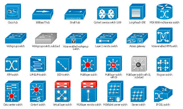
Cisco switches and hubs symbols
The vector stencils library "Vertex" contains 9 clipart icons of Vertex devices for drawing computer network diagrams and telecommunication equipment layouts.
"Vertex Standard is exclusively focused in offering a broad portfolio of analogue and digital two-way radios...
Products: Portable Radios, Mobile Radios, Repeaters / Base Stations, HF SSB Radios, APCO P25 Radios, Digital TDMA Radios (DMR), Trunking Radios." [vertex-standard-emea.com]
The clip art example "Vertex - Vector stencils library" was created using the ConceptDraw PRO diagramming and vector drawing software extended with the Telecommunication Network Diagrams solution from the Computer and Networks area of ConceptDraw Solution Park.
www.conceptdraw.com/ solution-park/ computer-networks-telecommunication
"Vertex Standard is exclusively focused in offering a broad portfolio of analogue and digital two-way radios...
Products: Portable Radios, Mobile Radios, Repeaters / Base Stations, HF SSB Radios, APCO P25 Radios, Digital TDMA Radios (DMR), Trunking Radios." [vertex-standard-emea.com]
The clip art example "Vertex - Vector stencils library" was created using the ConceptDraw PRO diagramming and vector drawing software extended with the Telecommunication Network Diagrams solution from the Computer and Networks area of ConceptDraw Solution Park.
www.conceptdraw.com/ solution-park/ computer-networks-telecommunication
VHF Marine Radio
Portable Radios
pmr446 Radio
VHF Marine Transceiver GX1270
Moibile Radios
p25 Transceiver
hf Radio
Base Stantion
Repeater
The vector stencils library "Cisco switches and hubs" contains 26 symbols of Cisco switches and hubs for drawing computer network diagrams.
"A switch is a device used on a computer network to physically connect devices together. Multiple cables can be connected to a switch to enable networked devices to communicate with each other. Switches manage the flow of data across a network by only transmitting a received message to the device for which the message was intended. Each networked device connected to a switch can be identified using a MAC address, allowing the switch to regulate the flow of traffic. This maximises security and efficiency of the network. Because of these features, a switch is often considered more "intelligent" than a network hub. Hubs neither provide security, or identification of connected devices. This means that messages have to be transmitted out of every port of the hub, greatly degrading the efficiency of the network." [Network switch. Wikipedia]
"An Ethernet hub, active hub, network hub, repeater hub, multiport repeater or hub is a device for connecting multiple Ethernet devices together and making them act as a single network segment. It has multiple input/ output (I/ O) ports, in which a signal introduced at the input of any port appears at the output of every port except the original incoming. A hub works at the physical layer (layer 1) of the OSI model. The device is a form of multiport repeater. Repeater hubs also participate in collision detection, forwarding a jam signal to all ports if it detects a collision." [Ethernet hub. Wikipedia]
The symbols example "Cisco switches and hubs - Vector stencils library" was created using the ConceptDraw PRO diagramming and vector drawing software extended with the Cisco Network Diagrams solution from the Computer and Networks area of ConceptDraw Solution Park.
www.conceptdraw.com/ solution-park/ computer-networks-cisco
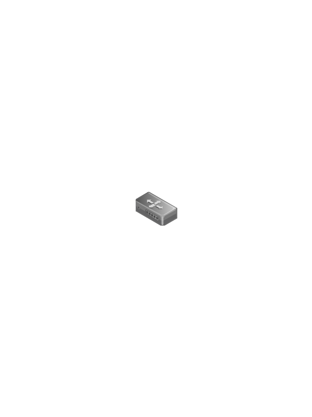
Cisco hub

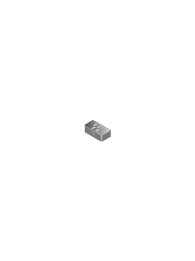
100BaseT hub

Small hub

Workgroup switch

Workgroup switch, subdued

Voice-enabled workgroup switch

ATM switch

LAN2LAN switch

ISDN switch

MGX 8000 multiservice switch

Multilayer switch with Si

Multilayer switch

Multilayer switch with Si, subdued

Program switch

Data center switch

Voice-enabled ATM switch

IP DSL switch

Content switch

Content service switch 1100

Virtual layer switch

Layer 2 remote switch

Server switch

Multilayer remote switch

Multifabric server switch

Access gateway

Long-Reach CPE

The vector stencils library "Cisco LAN" contains 23 symbols of local area network (LAN) devices and equipment for drawing Cisco LAN topology diagrams.
"Network topology describes the layout of interconnections between devices and network segments. At the Data Link Layer and Physical Layer, a wide variety of LAN topologies have been used, including ring, bus, mesh and star, but the most common LAN topology in use today is switched Ethernet. At the higher layers, the Internet Protocol (TCP/ IP) has become the standard, replacing NetBEUI, IPX/ SPX, AppleTalk and others.
Simple LANs generally consist of one or more switches. A switch can be connected to a router, cable modem, or ADSL modem for Internet access. Complex LANs are characterized by their use of redundant links with switches using the spanning tree protocol to prevent loops, their ability to manage differing traffic types via quality of service (QoS), and to segregate traffic with VLANs. A LAN can include a wide variety of network devices such as switches, firewalls, routers, load balancers, and sensors.
LANs can maintain connections with other LANs via leased lines, leased services, or the Internet using virtual private network technologies. Depending on how the connections are established and secured in a LAN, and the distance involved, a LAN may also be classified as a metropolitan area network (MAN) or a wide area network (WAN)." [Local area network. Wikipedia]
The symbols example "Cisco LAN - Vector stencils library" was created using the ConceptDraw PRO diagramming and vector drawing software extended with the Cisco Network Diagrams solution from the Computer and Networks area of ConceptDraw Solution Park.
www.conceptdraw.com/ solution-park/ computer-networks-cisco
"Network topology describes the layout of interconnections between devices and network segments. At the Data Link Layer and Physical Layer, a wide variety of LAN topologies have been used, including ring, bus, mesh and star, but the most common LAN topology in use today is switched Ethernet. At the higher layers, the Internet Protocol (TCP/ IP) has become the standard, replacing NetBEUI, IPX/ SPX, AppleTalk and others.
Simple LANs generally consist of one or more switches. A switch can be connected to a router, cable modem, or ADSL modem for Internet access. Complex LANs are characterized by their use of redundant links with switches using the spanning tree protocol to prevent loops, their ability to manage differing traffic types via quality of service (QoS), and to segregate traffic with VLANs. A LAN can include a wide variety of network devices such as switches, firewalls, routers, load balancers, and sensors.
LANs can maintain connections with other LANs via leased lines, leased services, or the Internet using virtual private network technologies. Depending on how the connections are established and secured in a LAN, and the distance involved, a LAN may also be classified as a metropolitan area network (MAN) or a wide area network (WAN)." [Local area network. Wikipedia]
The symbols example "Cisco LAN - Vector stencils library" was created using the ConceptDraw PRO diagramming and vector drawing software extended with the Cisco Network Diagrams solution from the Computer and Networks area of ConceptDraw Solution Park.
www.conceptdraw.com/ solution-park/ computer-networks-cisco
Sun workstation
Workstation
PC
Macintosh
Terminal
Mini VAX
Printer
Laptop
File server
Monitor
Web cluster
ATM fast gigabit etherswitch
HP Mini
Supercomputer
LAN2LAN
LAN to LAN
Web server
Web browser
Repeater
PDA
General appliance
PC, blue
Mini VAX, blue
Network Topologies

Ring Network Topology

Cisco LAN. Cisco icons, shapes, stencils and symbols

Network Glossary Definition


The vector stencils library "Wireless networks" contains 82 icon symbols for drawing wireless computer network diagrams and equipment layout plans.
"A wireless network is any type of computer network that uses wireless data connections for connecting network nodes.
Wireless networking is a method by which homes, telecommunications networks and enterprise (business) installations avoid the costly process of introducing cables into a building, or as a connection between various equipment locations.
Wireless telecommunications networks are generally implemented and administered using radio communication. This implementation takes place at the physical level (layer) of the OSI model network structure.
Examples of wireless networks include cell phone networks, Wi-Fi local networks and terrestrial microwave networks." [Wireless network. Wikipedia]
The clip art example "Wireless networks - Vector stencils library" was created using the ConceptDraw PRO diagramming and vector drawing software extended with the Wireless Networks solution from the Computer and Networks area of ConceptDraw Solution Park.
www.conceptdraw.com/ solution-park/ wireless-networks
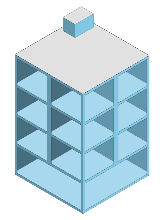
Building 1
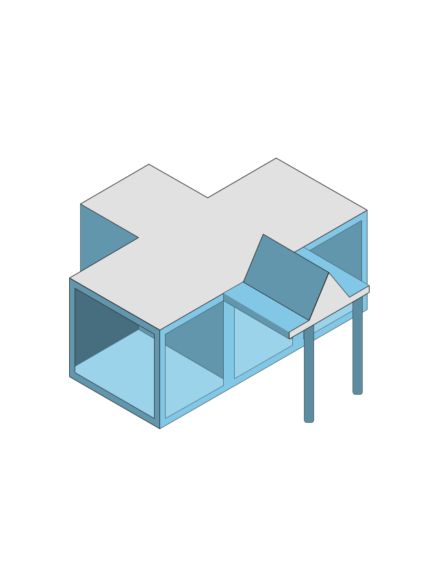
Building 4
Coverage (Blue)
-wireless-networks---vector-stencils-library.png--diagram-flowchart-example.png)
Wireless Connectivity

Network Cloud

Cloud

Wi-Fi Access

Tree

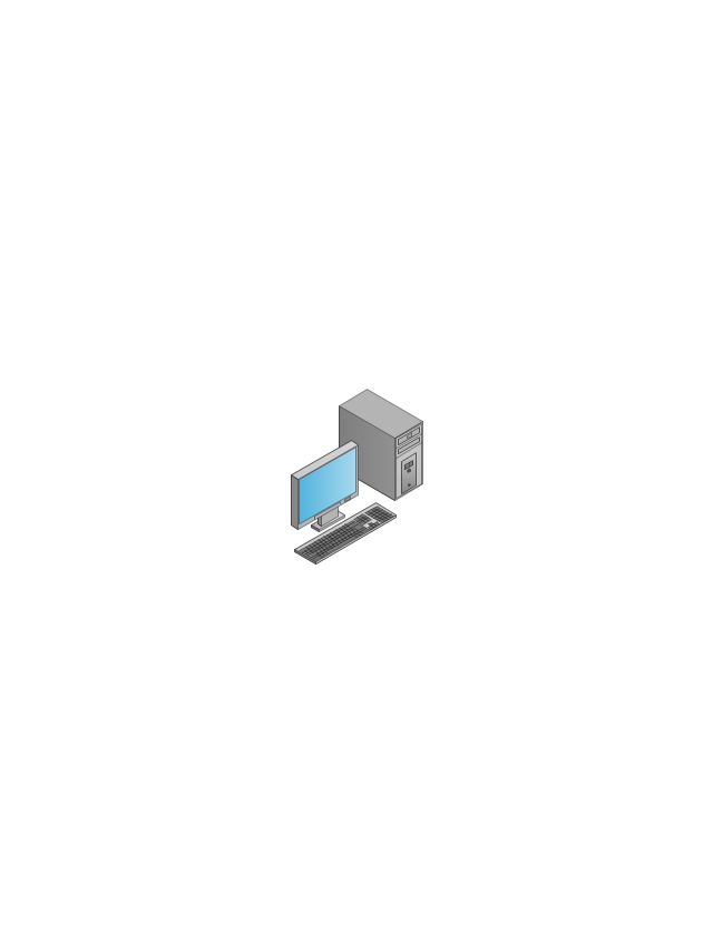
Computer
Laptop Computer

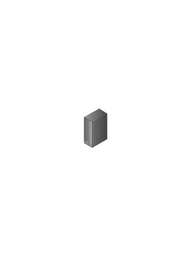
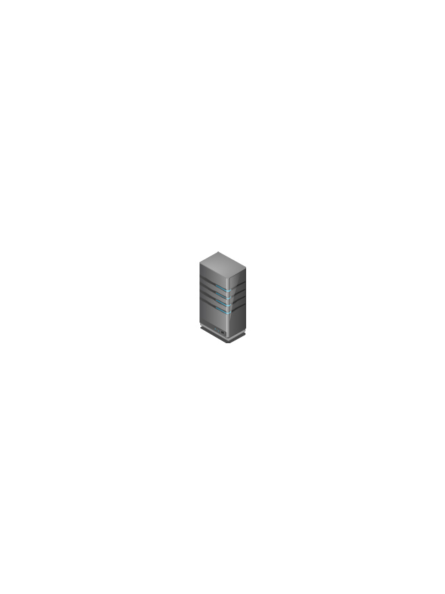
Server
Wireless Network Storage

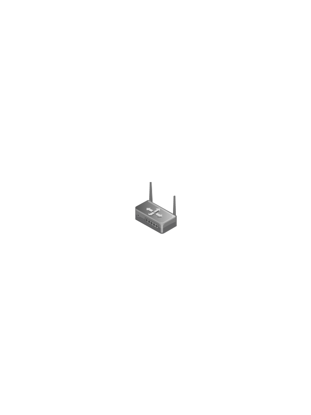
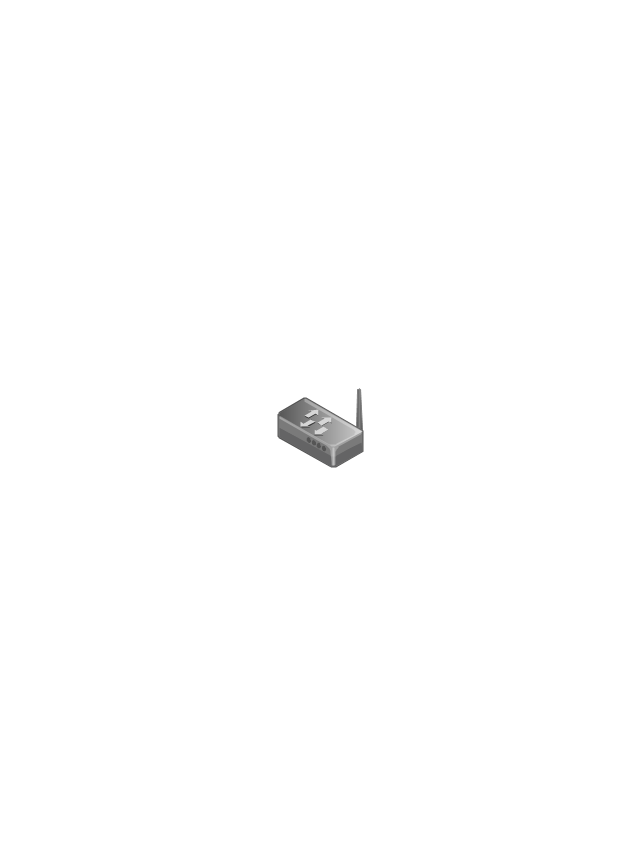
Router
Wireless Router
Switch
Wireless Access Point
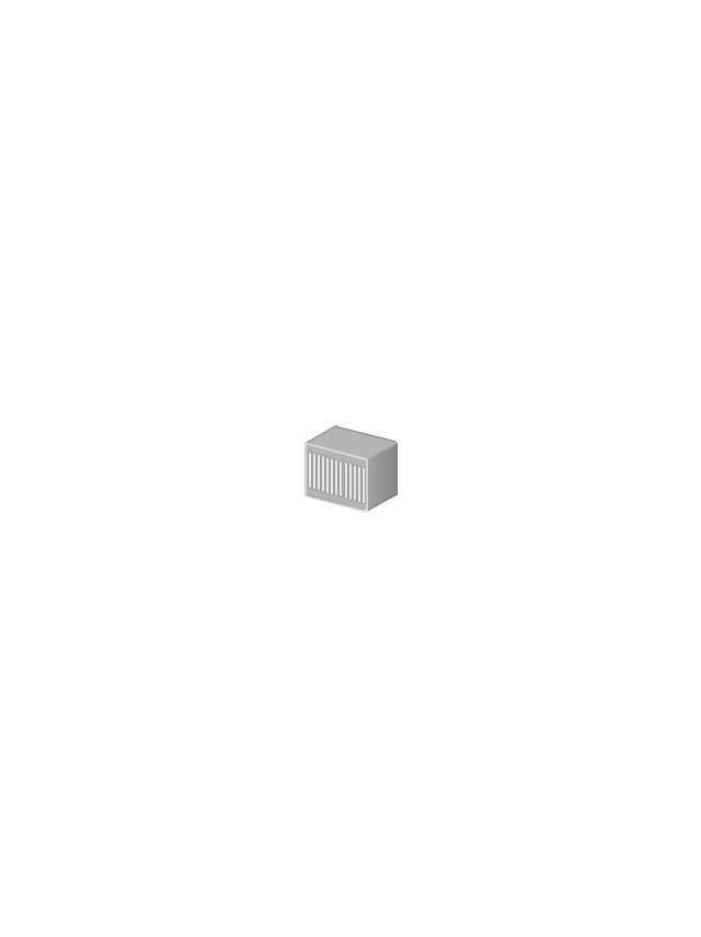
1U Hub Switch

2U Hub Switch
1U Server

2U Server

3U Server

4U Server

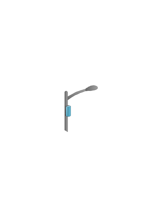
Outdoor Access Point
Indoor Access Point

Outdoor Wi-Fi Access Point

Access Point

Outdoor Mesh Node
Outdoor Mesh Node
Outdoor Access Node
Outdoor Access Node

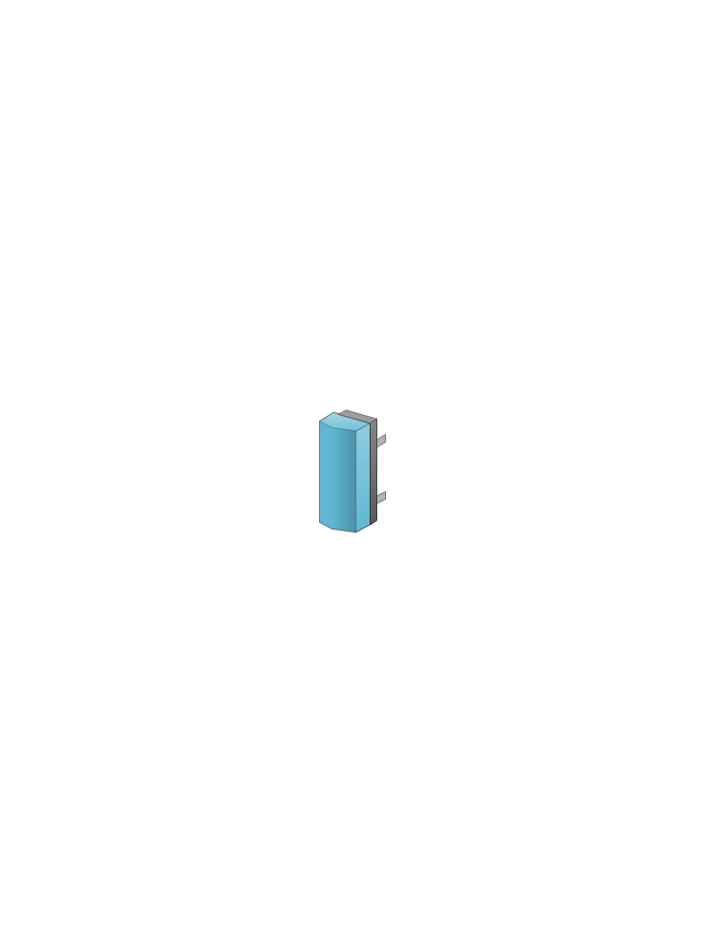
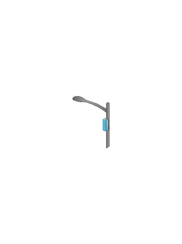
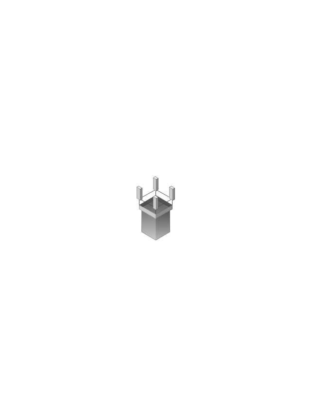
Base Station
Cellular Phone

Outdoor Mesh Node
Active Directory Server
Smart WLAN Controller

Smart WLAN Controller

Smart Wi-Fi Access Point
Indoor Wi-Fi Access Point

Firewall
Coverage (Yellow)
-wireless-networks---vector-stencils-library.png--diagram-flowchart-example.png)
Coverage (O-Shaped)
-wireless-networks---vector-stencils-library.png--diagram-flowchart-example.png)
Outdoor Mesh Node
The vector stencils library "Cisco LAN" contains 23 symbols of local area network (LAN) devices and equipment for drawing Cisco LAN topology diagrams.
"Network topology describes the layout of interconnections between devices and network segments. At the Data Link Layer and Physical Layer, a wide variety of LAN topologies have been used, including ring, bus, mesh and star, but the most common LAN topology in use today is switched Ethernet. At the higher layers, the Internet Protocol (TCP/ IP) has become the standard, replacing NetBEUI, IPX/ SPX, AppleTalk and others.
Simple LANs generally consist of one or more switches. A switch can be connected to a router, cable modem, or ADSL modem for Internet access. Complex LANs are characterized by their use of redundant links with switches using the spanning tree protocol to prevent loops, their ability to manage differing traffic types via quality of service (QoS), and to segregate traffic with VLANs. A LAN can include a wide variety of network devices such as switches, firewalls, routers, load balancers, and sensors.
LANs can maintain connections with other LANs via leased lines, leased services, or the Internet using virtual private network technologies. Depending on how the connections are established and secured in a LAN, and the distance involved, a LAN may also be classified as a metropolitan area network (MAN) or a wide area network (WAN)." [Local area network. Wikipedia]
The symbols example "Cisco LAN - Vector stencils library" was created using the ConceptDraw PRO diagramming and vector drawing software extended with the Cisco Network Diagrams solution from the Computer and Networks area of ConceptDraw Solution Park.
www.conceptdraw.com/ solution-park/ computer-networks-cisco
"Network topology describes the layout of interconnections between devices and network segments. At the Data Link Layer and Physical Layer, a wide variety of LAN topologies have been used, including ring, bus, mesh and star, but the most common LAN topology in use today is switched Ethernet. At the higher layers, the Internet Protocol (TCP/ IP) has become the standard, replacing NetBEUI, IPX/ SPX, AppleTalk and others.
Simple LANs generally consist of one or more switches. A switch can be connected to a router, cable modem, or ADSL modem for Internet access. Complex LANs are characterized by their use of redundant links with switches using the spanning tree protocol to prevent loops, their ability to manage differing traffic types via quality of service (QoS), and to segregate traffic with VLANs. A LAN can include a wide variety of network devices such as switches, firewalls, routers, load balancers, and sensors.
LANs can maintain connections with other LANs via leased lines, leased services, or the Internet using virtual private network technologies. Depending on how the connections are established and secured in a LAN, and the distance involved, a LAN may also be classified as a metropolitan area network (MAN) or a wide area network (WAN)." [Local area network. Wikipedia]
The symbols example "Cisco LAN - Vector stencils library" was created using the ConceptDraw PRO diagramming and vector drawing software extended with the Cisco Network Diagrams solution from the Computer and Networks area of ConceptDraw Solution Park.
www.conceptdraw.com/ solution-park/ computer-networks-cisco
Sun workstation
Workstation
PC
Macintosh
Terminal
Mini VAX
Printer
Laptop
File server
Monitor
Web cluster
ATM fast gigabit etherswitch
HP Mini
Supercomputer
LAN2LAN
LAN to LAN
Web server
Web browser
Repeater
PDA
General appliance
PC, blue
Mini VAX, blue
"In computer networks, networked computing devices pass data to each other along data connections. The connections (network links) between nodes are established using either cable media or wireless media. ...
Network computer devices that originate, route and terminate the data are called network nodes. Nodes can include hosts such as personal computers, phones, servers as well as networking hardware. ...
Network links.
The communication media used to link devices to form a computer network include electrical cable (HomePNA, power line communication, G.hn), optical fiber (fiber-optic communication), and radio waves (wireless networking). In the OSI model, these are defined at layers 1 and 2 - the physical layer and the data link layer.
A widely adopted family of communication media used in local area network (LAN) technology is collectively known as Ethernet. The media and protocol standards that enable communication between networked devices over Ethernet are defined by IEEE 802.3. Ethernet transmit data over both copper and fiber cables. Wireless LAN standards (e.g. those defined by IEEE 802.11) use radio waves, or others use infrared signals as a transmission medium. Power line communication uses a building's power cabling to transmit data. ...
Network nodes.
Apart from the physical communications media described above, networks comprise additional basic system building blocks, such as network interface controller (NICs), repeaters, hubs, bridges, switches, routers, modems, and firewalls." [Computer network. Wikipedia]
The network equipment and cabling layout floorplan template for the ConceptDraw PRO diagramming and vector drawing software is included in the Network Layout Floor Plans solution from the Computer and Networks area of ConceptDraw Solution Park.
LAN equipment and cabling layout floorplan template

Digital Communications Network. Computer and Network Examples

- 2 - way repeater , bypass, 1 line
- 2-way repeater , 4-wire, 4 lines
- Using A Diagram Illustrate The Design Of Lan Constituting A Switch ...
- Diagram Of A Local Area Network Consisting Switch Repeater ...
- Diagram Design Of A Lan Constituting Of A Bridge Switch Repeater ...
- How Does 2 Way Repeater 4 Wire 4 Lines
- Repeater
- Repeater
- Stations - Vector stencils library
- Design elements - Composite assemblies | Design elements ...
- Network Hubs | Computer network - Vector stencils library ...
- Symbol For Repeater
- Composite assemblies - Vector stencils library
- Cisco Switches and Hubs. Cisco icons, shapes, stencils and symbols
- Cisco switches and hubs - Vector stencils library | Cisco LAN ...
- How To use Switches in Network Diagram | ConceptDraw PRO ...
- Network Hubs | Cisco Switches and Hubs. Cisco icons, shapes ...
- Cisco Switches and Hubs. Cisco icons, shapes, stencils and ...
- Cisco switches and hubs - Vector stencils library | Cisco switches ...
- Tool for Workgroup Briefings, Meetings and Decisions | How To ...