The vector stencils library "Fluid power valves" contains 93 symbols of pre-made hydraulic and pneumatic valves, including directional control valves, flow control valves, pressure control valves, and electrohydraulic and electropneumatic valves.
Use these shapes to design fluid power diagrams in the ConceptDraw PRO diagramming and vector drawing software extended with the Mechanical Engineering solution from the Engineering area of ConceptDraw Solution Park.
www.conceptdraw.com/ solution-park/ engineering-mechanical
Use these shapes to design fluid power diagrams in the ConceptDraw PRO diagramming and vector drawing software extended with the Mechanical Engineering solution from the Engineering area of ConceptDraw Solution Park.
www.conceptdraw.com/ solution-park/ engineering-mechanical
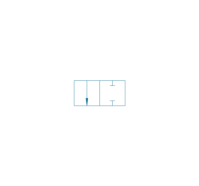
2/2 valve, pneum., finite positions

2/2 valve, pneum., infinite positions
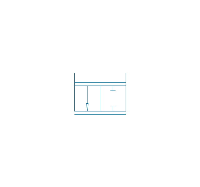
2/2 valve, pneum., ext., fin. pos.
2/2 valve, pneum., ext., infin. pos.
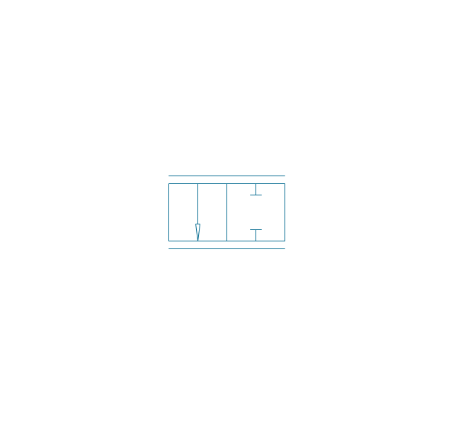
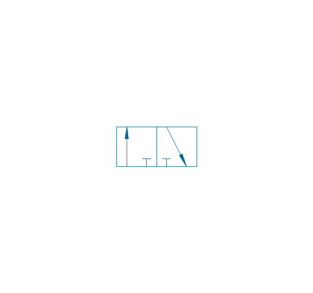
2/2 valve, hydr., finite positions
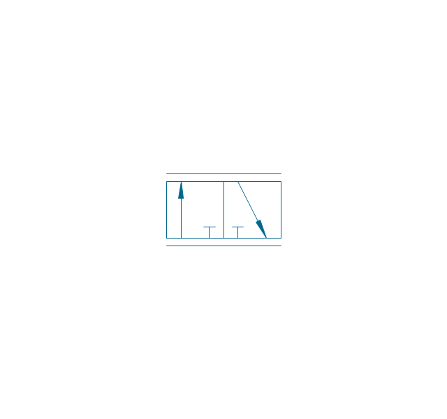
2/2 valve, hydr., infinite positions

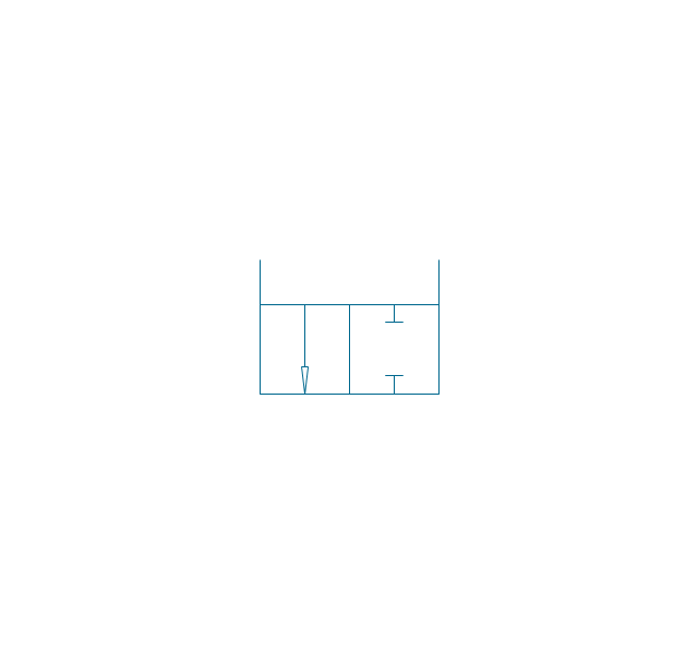
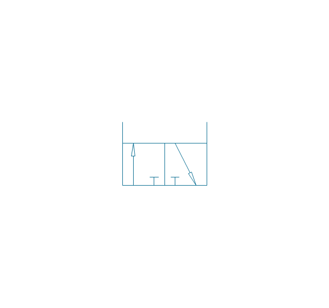
2/2 valve, hydr., ext., fin. pos.
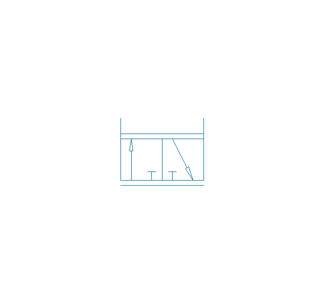
2/2 valve, hydr., ext., infin. pos.
3/2 valve, pneum., finite positions
3/2 valve, pneum., infinite positions
3/2 valve, pneum., ext., fin. pos.
3/2 valve, pneum., ext., infin. pos.
3/2 valve, hydr., finite positions
3/2 valve, hydr., infinite positions
3/2 valve, hydr., ext., fin. pos.
3/2 valve, hydr., ext., infin. pos.
4/2 valve, pneum., finite positions

4/2 valve, pneum., infinite positions
4/2 valve, pneum., ext., fin. pos.
4/2 valve, pneum., ext., infin. pos.
4/2 valve, hydr., finite positions

4/2 valve, hydr., infinite positions

4/2 valve, hydr., ext., fin. pos.

4/2 valve, hydr., ext., infin. pos.
5/2 valve, pneum., finite positions
5/2 valve, pneum., infinite positions
5/2 valve, pneum., ext., fin. pos.

5/2 valve, pneum., ext., infin. pos.

5/2 valve, hydr., finite positions

5/2 valve, hydr., infinite positions

5/2 valve, hydr., ext., fin. pos.
5/2 valve, hydr., ext., infin. pos.
4/3 valve, pneum., finite positions

4/3 valve, pneum., infinite positions
4/3 valve, pneum., ext., fin. pos.
4/3 valve, pneum., ext., infin. pos.
4/3 valve, hydr., finite positions

4/3 valve, hydr., infinite positions

4/3 valve, hydr., ext., fin. pos.
4/3 valve, hydr., ext., infin. pos.
5/3 valve, pneum., finite positions
5/3 valve, pneum., infinite positions
5/3 valve, pneum., ext., fin. pos.
5/3 valve, pneum., ext., infin. pos.
5/3 valve, hydr., finite positions
5/3 valve, hydr., infinite positions
5/3 valve, hydr., ext., fin. pos.
5/3 valve, hydr., ext., infin. pos.
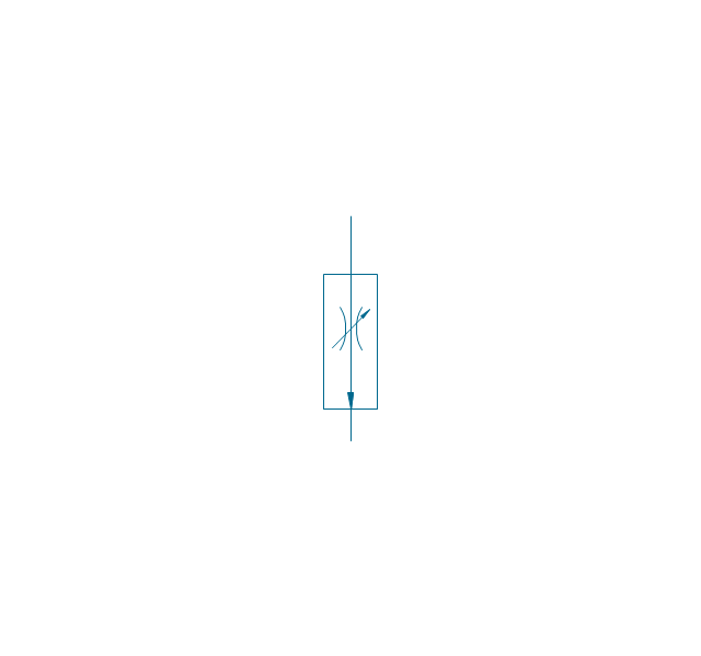
Restrictor valve
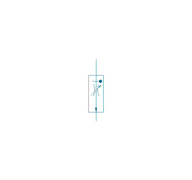
Restrictor valve, adjustable
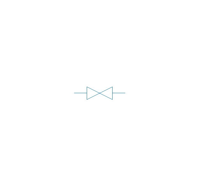
Gate-valve, norm. open
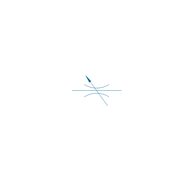
Gate-valve, norm. open, adj.
Gate-valve, norm. closed

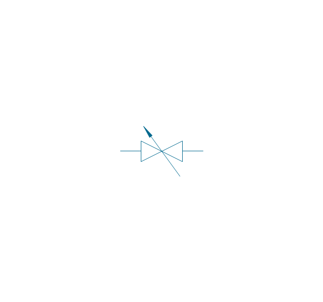
Gate-valve, norm. closed, adj.

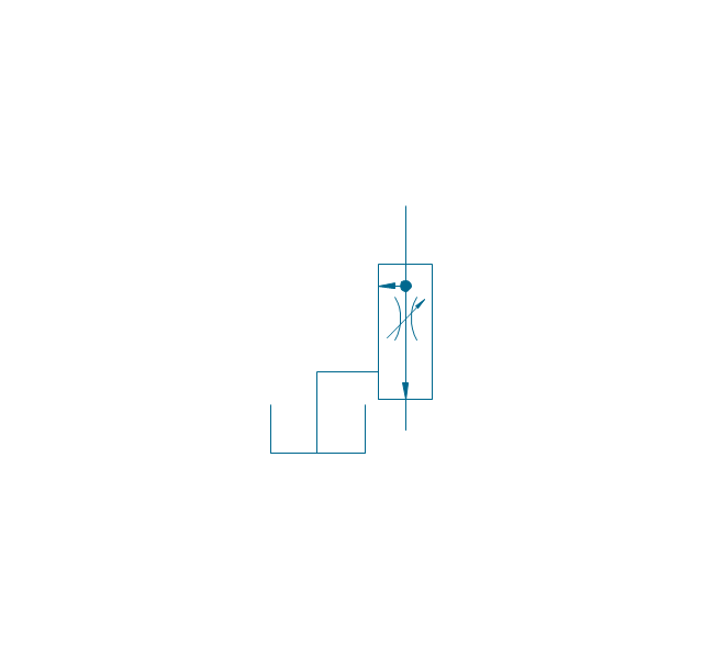
One-way restrictor
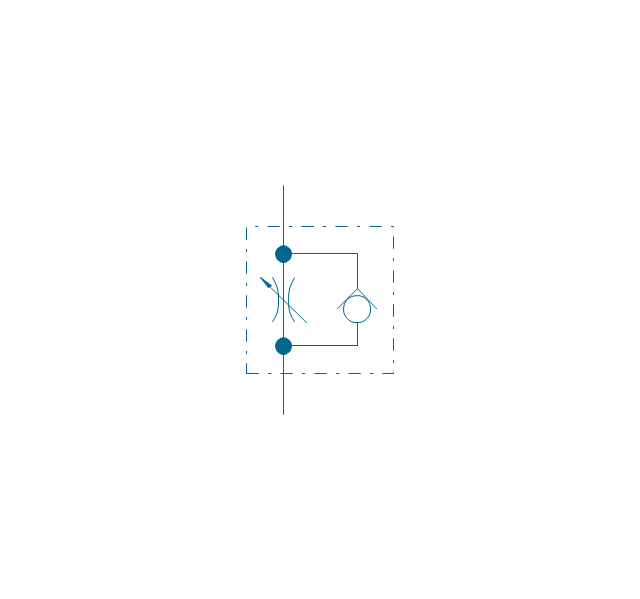
One-way restrictor, enclosed
Flow control, series flow
Flow control, temperature compensated
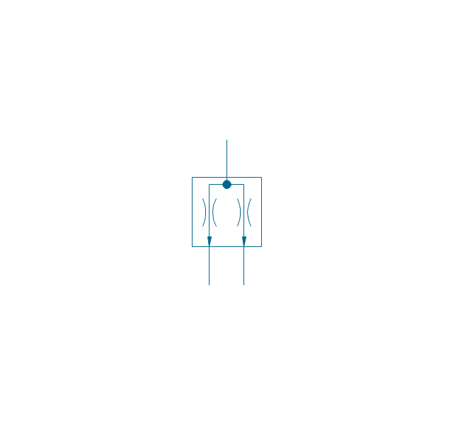
Flow control, bypass flow
Flow divider
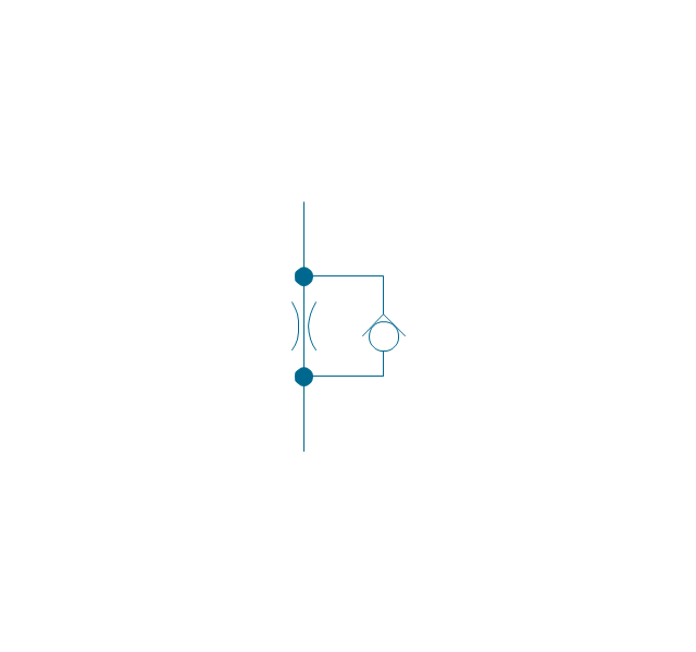
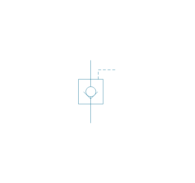
Non-return, pilot controlled
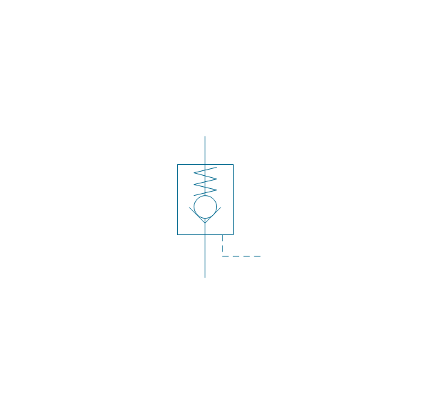
Non-return, pilot contr., spring
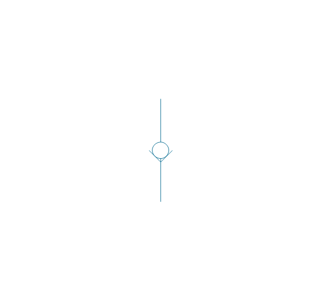
Non-return, free
Non-return, spring loaded
Coupling (connect.), 1 valve
,-1-valve-fluid-power-valves---vector-stencils-library.png--diagram-flowchart-example.png)
Coupling (connect.), both valves
,-both-valves-fluid-power-valves---vector-stencils-library.png--diagram-flowchart-example.png)
Coupling (connect.), no valves
,-no-valves-fluid-power-valves---vector-stencils-library.png--diagram-flowchart-example.png)
Coupling (connect.), 1 valve, encl.
,-1-valve,-encl.-fluid-power-valves---vector-stencils-library.png--diagram-flowchart-example.png)
Coupling (connect.), both valves, encl.
,-both-valves,-encl.-fluid-power-valves---vector-stencils-library.png--diagram-flowchart-example.png)
Coupling (connect.), no valves, encl.
,-no-valves,-encl.-fluid-power-valves---vector-stencils-library.png--diagram-flowchart-example.png)
Coupling (discon.), 1 valve
,-1-valve-fluid-power-valves---vector-stencils-library.png--diagram-flowchart-example.png)
Coupling (discon.), both valves
,-both-valves-fluid-power-valves---vector-stencils-library.png--diagram-flowchart-example.png)
Coupling (discon.), no valves
,-no-valves-fluid-power-valves---vector-stencils-library.png--diagram-flowchart-example.png)
Coupling (discon.), 1 valve, encl.
,-1-valve,-encl.-fluid-power-valves---vector-stencils-library.png--diagram-flowchart-example.png)
Coupling (discon.), both valves, encl.
,-both-valves,-encl.-fluid-power-valves---vector-stencils-library.png--diagram-flowchart-example.png)
Coupling (discon.), no valves, encl.
,-no-valves,-encl.-fluid-power-valves---vector-stencils-library.png--diagram-flowchart-example.png)
Shuttle valve
Priority shuttle valve
Quick exhaust
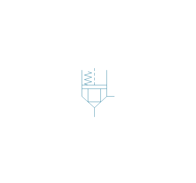
Cartridge valve
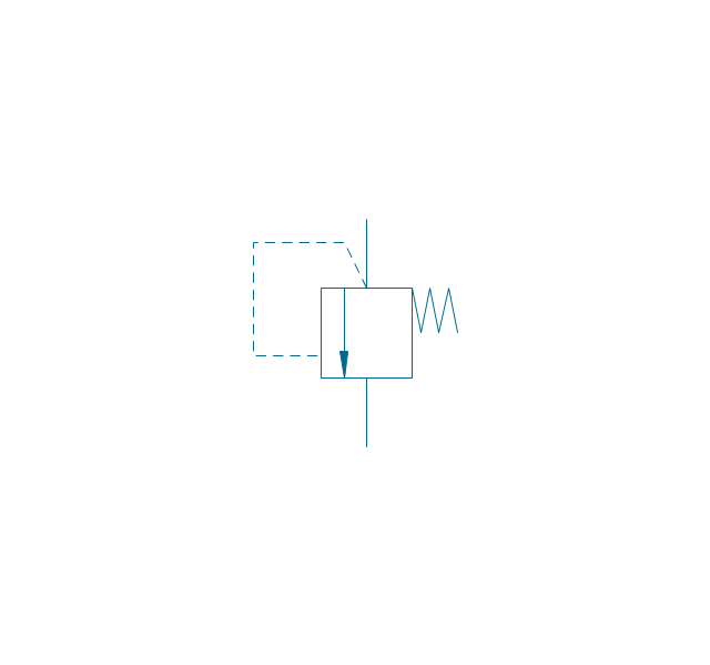
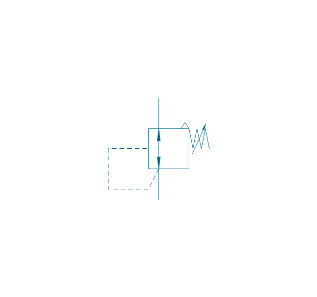
Pressure relief
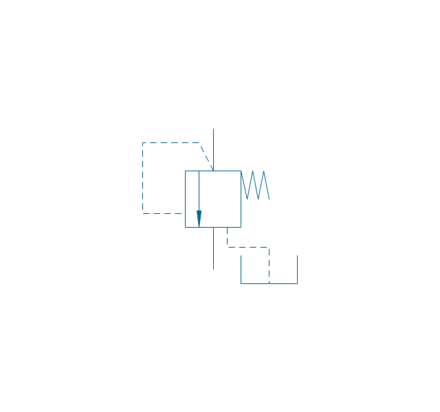
Pressure relief, drain
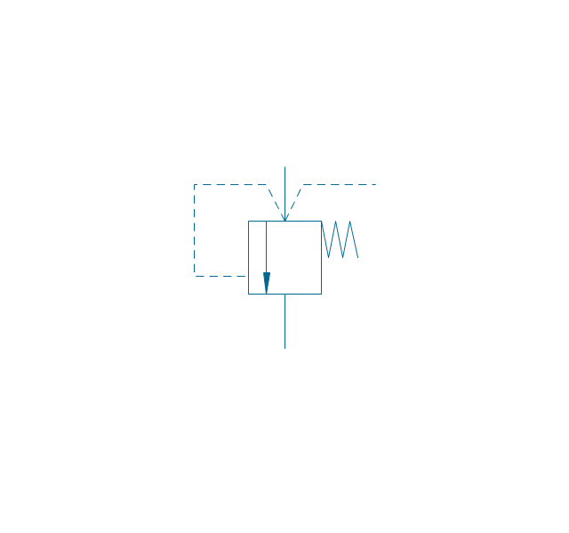
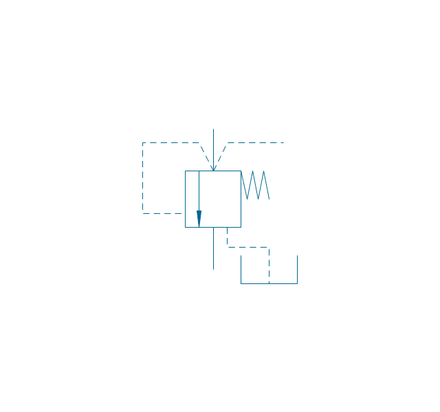
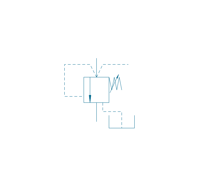
Pressure relief, vent port
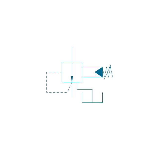
Pressure relief, drain, vent port
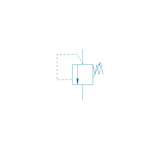
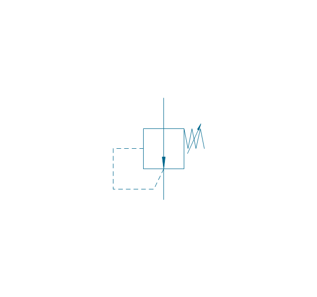
Pressure relief, var.
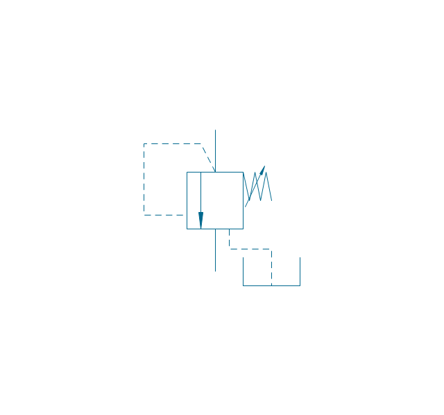
Pressure relief, var., drain
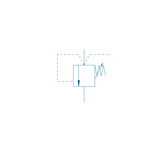
Pressure relief, var., vent port
Pressure relief, var., drain, vent port
Pressure relief 2
Pressure reducing, 1 stage
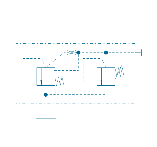
Pressure reducing, 2 stage
Pressure reducing, relief
Pressure relief (E)
-fluid-power-valves---vector-stencils-library.png--diagram-flowchart-example.png)
Mechanical Drawing Symbols

The vector stencils library "Valve assembly" contains 141 symbols of pressure and flow regulators, flow direction indicators, controls, and symbols to design flow paths of control valves.
Use these valve assembly shapes to design the engineering drawings of hydraulic and pneumatic valve assemblies in fluid power systems.
"Control valves are valves used to control conditions such as flow, pressure, temperature, and liquid level by fully or partially opening or closing in response to signals received from controllers that compare a "setpoint" to a "process variable" whose value is provided by sensors that monitor changes in such conditions.
The opening or closing of control valves is usually done automatically by electrical, hydraulic or pneumatic actuators. Positioners are used to control the opening or closing of the actuator based on electric, or pneumatic signals.
A control valve consists of three main parts in which each part exist in several types and designs: Valve's actuator, Valve's positioner, Valve's body.
" [Control valves. Wikipedia]
The shapes example "" was created using the ConceptDraw PRO diagramming and vector drawing software extended with the Mechanical Engineering solution from the Engineering area of ConceptDraw Solution Park.
Valve assembly symbols

The vector stencils library "Fluid power valves" contains 93 symbols of pre-made hydraulic and pneumatic valves, including directional control valves, flow control valves, pressure control valves, and electrohydraulic and electropneumatic valves.
"Control valves are valves used to control conditions such as flow, pressure, temperature, and liquid level by fully or partially opening or closing in response to signals received from controllers that compare a "setpoint" to a "process variable" whose value is provided by sensors that monitor changes in such conditions.
The opening or closing of control valves is usually done automatically by electrical, hydraulic or pneumatic actuators. Positioners are used to control the opening or closing of the actuator based on electric, or pneumatic signals.
A control valve consists of three main parts in which each part exist in several types and designs: Valve's actuator, Valve's positioner, Valve's body.
" [Control valves. Wikipedia]
The shapes example "Design elements - Fluid power valves" was created using the ConceptDraw PRO diagramming and vector drawing software extended with the Mechanical Engineering solution from the Engineering area of ConceptDraw Solution Park.
Fluid power valve symbols

The vector stencils library "Valve assembly" contains 141 symbols of pressure and flow regulators, flow direction indicators, controls, and symbols to design flow paths of control valves in fluid power systems.
Use these valve assembly shapes to design the engineering drawings of hydraulic and pneumatic valve assemblies
in the ConceptDraw PRO diagramming and vector drawing software extended with the Mechanical Engineering solution from the Engineering area of ConceptDraw Solution Park.
www.conceptdraw.com/ solution-park/ engineering-mechanical
2 position 2,3,4 port (fin. pos.)
-valve-assembly---vector-stencils-library.png--diagram-flowchart-example.png)
2 position 2,3,4 port (infin. pos.)
-valve-assembly---vector-stencils-library.png--diagram-flowchart-example.png)
2 position 2,3,4 port (ext., fin.pos.)
-valve-assembly---vector-stencils-library.png--diagram-flowchart-example.png)
2 position 2,3,4 port (ext., infin. pos.)
-valve-assembly---vector-stencils-library.png--diagram-flowchart-example.png)
2 position 5 port (fin. pos.)
-valve-assembly---vector-stencils-library.png--diagram-flowchart-example.png)
2 position 5 port (infin. pos.)
-valve-assembly---vector-stencils-library.png--diagram-flowchart-example.png)
2 position 5 port (ext., fin.pos.)
-valve-assembly---vector-stencils-library.png--diagram-flowchart-example.png)
2 position 5 port (ext., infin. pos.)
-valve-assembly---vector-stencils-library.png--diagram-flowchart-example.png)
3 position 2,3,4 port (fin. pos.)
-valve-assembly---vector-stencils-library.png--diagram-flowchart-example.png)
3 position 2,3,4 port (infin. pos.)
-valve-assembly---vector-stencils-library.png--diagram-flowchart-example.png)
3 position 2,3,4 port (ext., fin.pos.)
-valve-assembly---vector-stencils-library.png--diagram-flowchart-example.png)
3 position 2,3,4 port (ext., infin. pos.)
-valve-assembly---vector-stencils-library.png--diagram-flowchart-example.png)
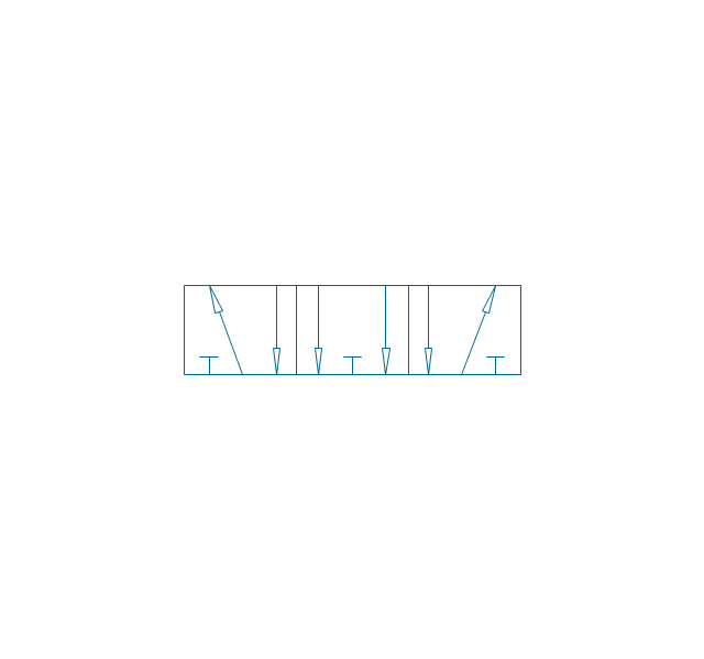
3 position 5 port (fin. pos.)
-valve-assembly---vector-stencils-library.png--diagram-flowchart-example.png)
3 position 5 port (infin. pos.)
-valve-assembly---vector-stencils-library.png--diagram-flowchart-example.png)
3 position 5 port (ext., fin.pos.)
-valve-assembly---vector-stencils-library.png--diagram-flowchart-example.png)
3 position 5 port (ext., infin. pos.)
-valve-assembly---vector-stencils-library.png--diagram-flowchart-example.png)
4 position 2,3,4 port (fin. pos.)
-valve-assembly---vector-stencils-library.png--diagram-flowchart-example.png)
4 position 2,3,4 port (infin. pos.)
-valve-assembly---vector-stencils-library.png--diagram-flowchart-example.png)
4 position 2,3,4 port (ext., fin.pos.)
-valve-assembly---vector-stencils-library.png--diagram-flowchart-example.png)
4 position 2,3,4 port (ext., infin. pos.)
-valve-assembly---vector-stencils-library.png--diagram-flowchart-example.png)
4 position 5 port (fin. pos.)
-valve-assembly---vector-stencils-library.png--diagram-flowchart-example.png)
4 position 5 port (infin. pos.)
-valve-assembly---vector-stencils-library.png--diagram-flowchart-example.png)
4 position 5 port (ext., fin.pos.)
-valve-assembly---vector-stencils-library.png--diagram-flowchart-example.png)
4 position 5 port (ext., infin. pos.)
-valve-assembly---vector-stencils-library.png--diagram-flowchart-example.png)
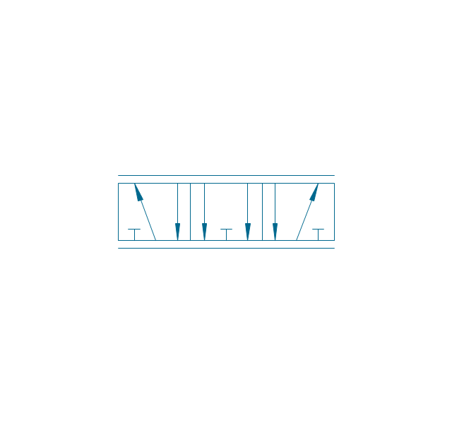
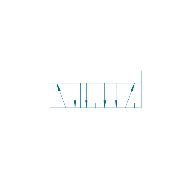
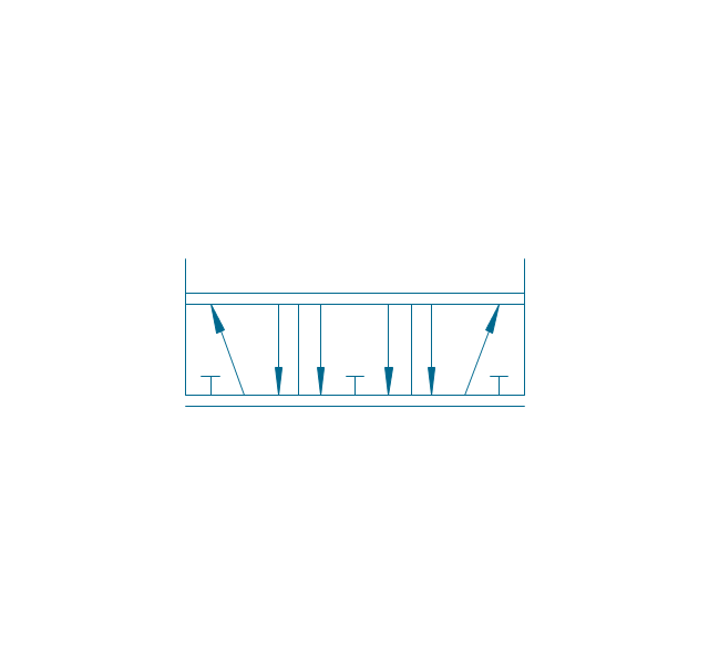
Box 5 port
Box 2,3,4 port
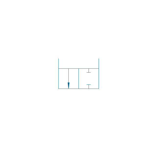
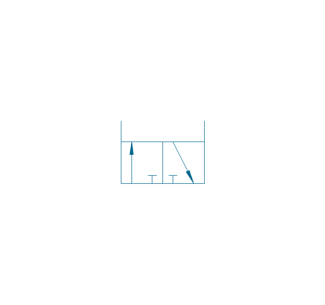
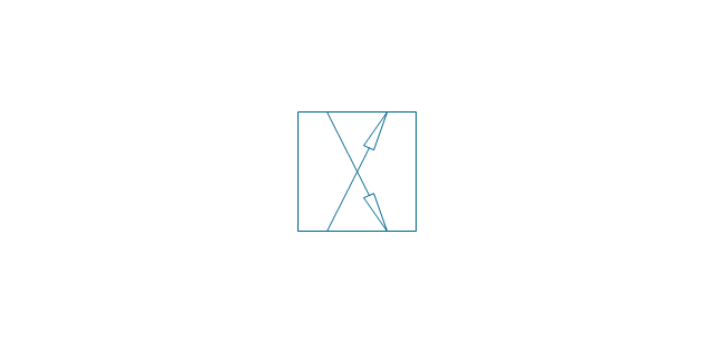
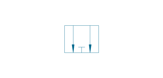
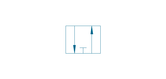
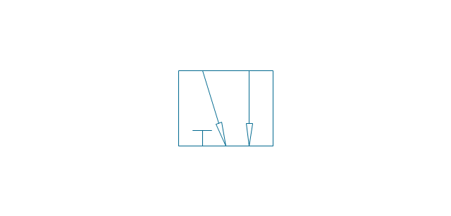
2-port, pneum., 1 arrow
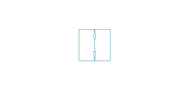
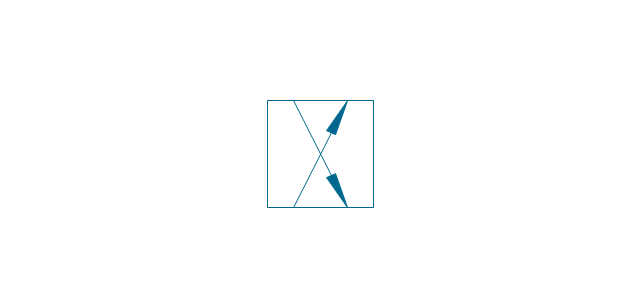
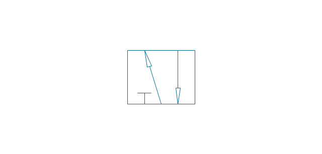
2-port, pneum., 2 arrows
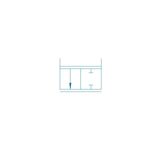
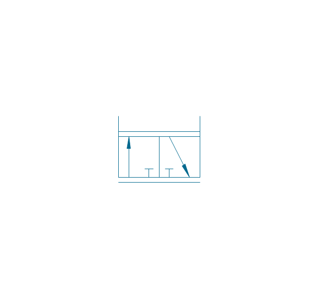
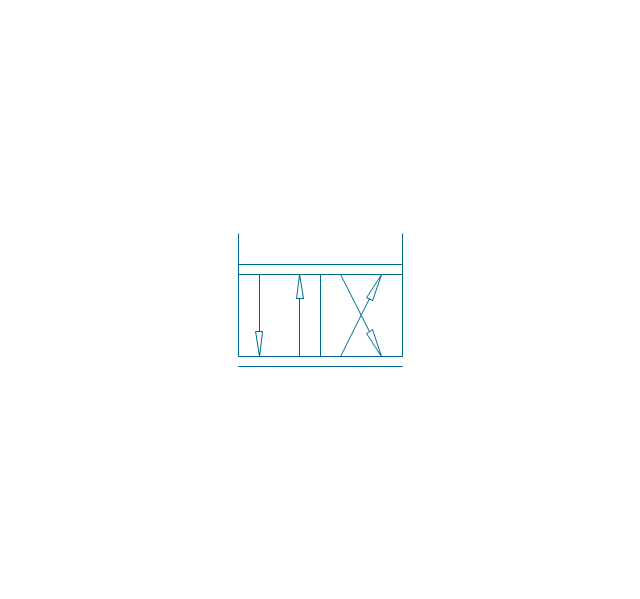
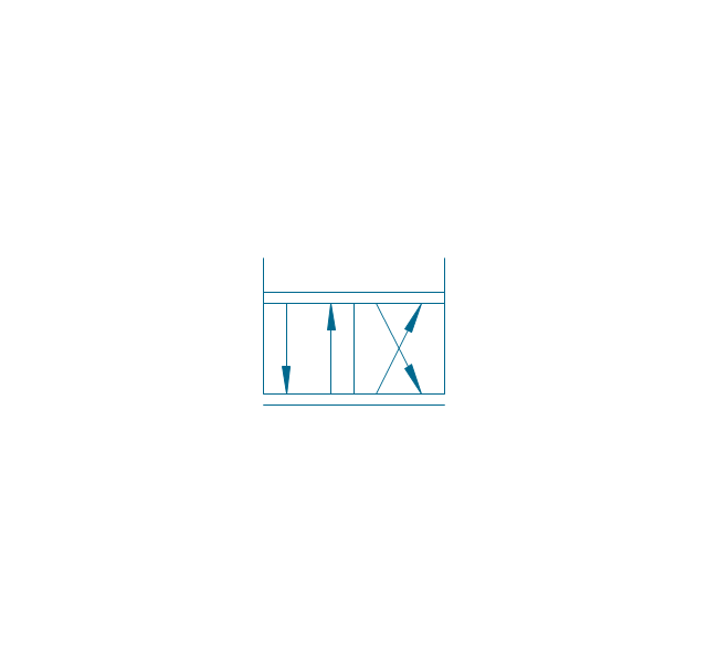
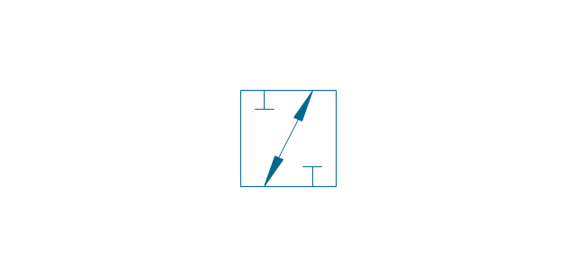
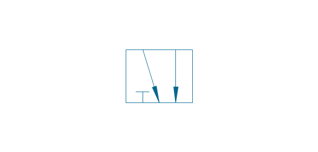
2-port, hydr., 1 arrow
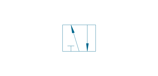
2-port, hydr., 2 arrows
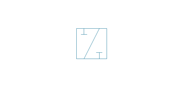
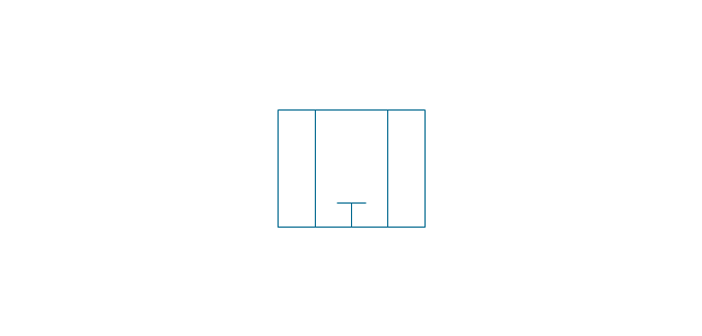
2-port
2-port closed
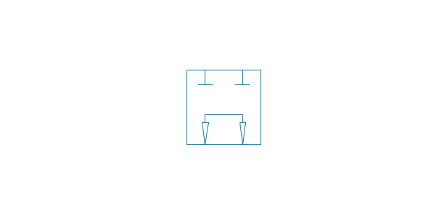
3-port, pneum., 1 arrow
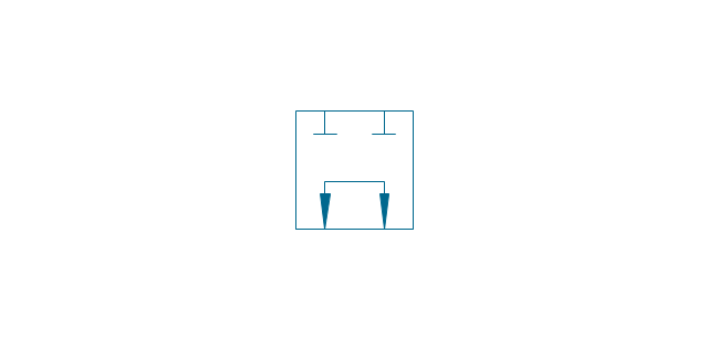
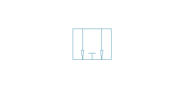
3-port, pneum., 2 arrows
3-port, hydr., 1 arrow
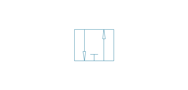
3-port, hydr., 2 arrows
3-port
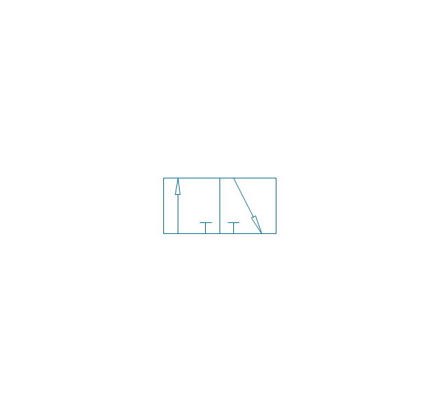
3-port crossover, pneum., 1 arrow
3-port crossover, pneum., 2 arrows
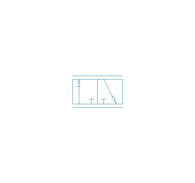
3-port crossover, hydr., 1 arrow
3-port crossover, hydr., 2 arrows
3-port crossover
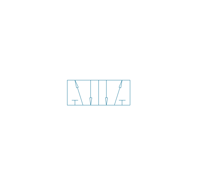
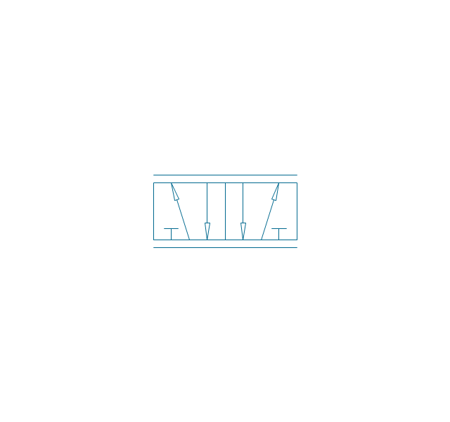
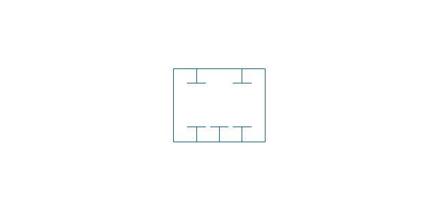
4-port, pneum.
4-port, hydr.
4-port closed
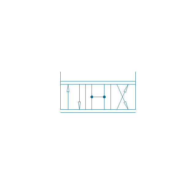
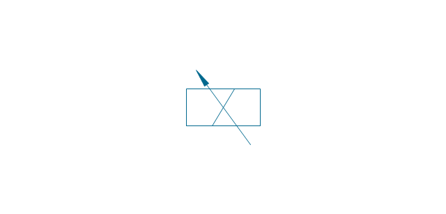
4-port crossed, pneum.
4-port crossed, hydr.
4-port tandem, pneum., 1 arrow
4-port tandem, pneum., 2 arrows
4-port tandem, hydr., 1 arrow
4-port tandem, hydr., 2 arrows
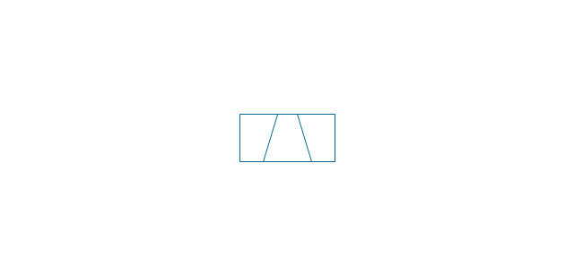
4-port tandem
4-port open
4-port semi-connected
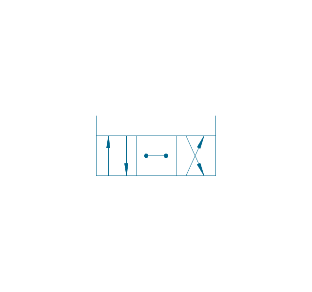
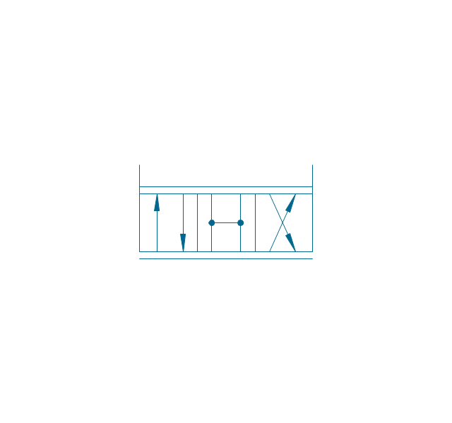
4-port crossover, pneum., 1 arrow
4-port crossover, pneum., 2 arrows
4-port crossover, hydr., 1 arrow
4-port crossover, hydr., 2 arrows
4-port crossover
5-port, pneum., arrows same
5-port, pneum., arrows opposite
5-port, hydr., arrows same
5-port, hydr., arrows opposite
5-port
5-port closed
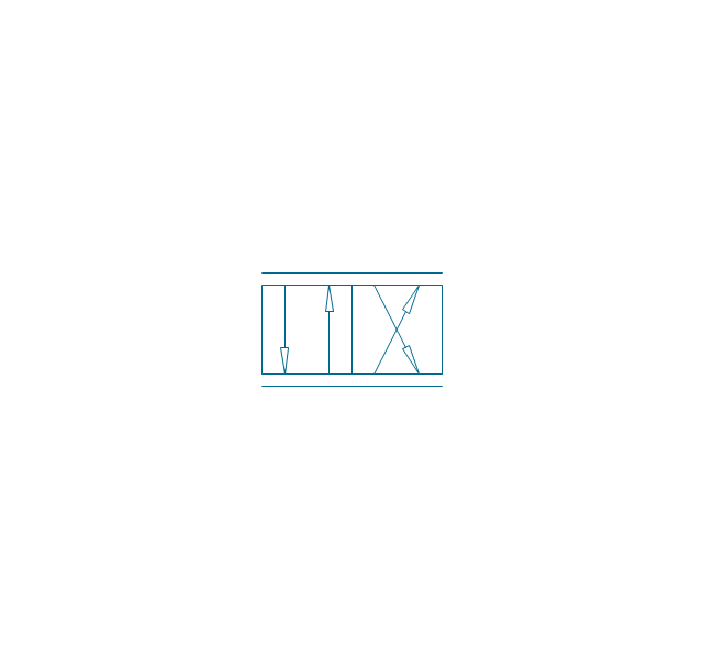
5-port crossover, pneum., arrows same
5-port crossover, pneum., arrows opposite
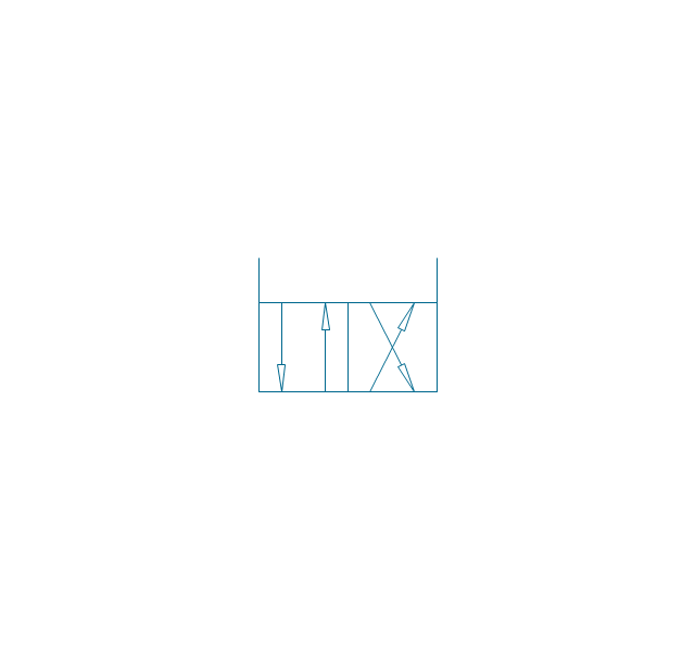
5-port crossover, hydr., arrows same
5-port crossover, hydr., arrows opposite
5-port crossover
Spring

Spring, var.
Plunger

Plunger, var.
Roller

Roller (arrow)
-valve-assembly---vector-stencils-library.png--diagram-flowchart-example.png)
One-way trip
One-way trip (arrow)
-valve-assembly---vector-stencils-library.png--diagram-flowchart-example.png)
Manual override

Pull button
Push button
Pull/push button
Lever
Pedal

Treadle
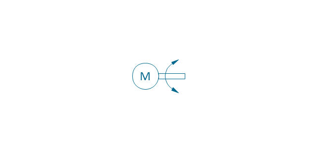
Electric rotor
Electric control, proportional, 1 winding
Electric control, proportional, 2 windings

Electric control, non-proportional, 1 winding

Electric control, non-proportional, 2 windings
Pilot-operated, pneum., 1 arrow, points left
Pilot-operated, pneum., 1 arrow, points right

Pilot-operated, pneum., 2 arrows, points left
Pilot-operated, pneum., 2 arrows, points right

Pilot-operated, pneum.

Pilot-operated, hydr., 1 arrow, points left

Pilot-operated, hydr., 1 arrow, points right

Pilot-operated, hydr., 2 arrows, points left

Pilot-operated, hydr., 2 arrows, points right

Pilot-operated, hydr.

Detent

Junction dot

T-junction, con.
T-junction, discon.
4-way junction, con.
4-way junction, discon.
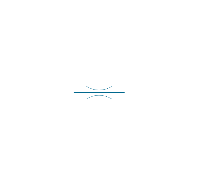
Crossing
Flexible line
Air bleed, continuous
Air bleed, temporary

Fluid energy

Fluid energy, hydr.

Fluid energy, pneum.

Air exhaust port

Fluid flow, pneum.
Fluid flow, hydr.
Rotary connection (1)
-valve-assembly---vector-stencils-library.png--diagram-flowchart-example.png)
Rotary connection (3)
-valve-assembly---vector-stencils-library.png--diagram-flowchart-example.png)
Variable arrow
Curved arrow, top

Curved arrow, bottom

Curved arrow, both ends

Flow path

Flow path, pneum., 1 arrow
Flow path, hydr., 1 arrow
Flow path, pneum., 2 arrows

Flow path, hydr., 2 arrows

Shaft, top arrow
Shaft, bottom arrow
Shaft, both arrows
Shaft
Rod, right arrow
Rod, left arrow
Rod, both arrows
Over - center
Latch
Closed path

Electric
Restriction

Closed path (double)
-valve-assembly---vector-stencils-library.png--diagram-flowchart-example.png)
Temperature

Process Flow Diagram Symbols

Electrical Symbols — Rotating Equipment

Interior Design. Piping Plan — Design Elements

The vector stencils library "Valves and fittings" contains 104 symbols of valve components.
Use these icons for drawing industrial piping systems; process, vacuum, and fluids piping; hydraulics piping; air and gas piping; materials distribution; and liquid transfer systems in the ConceptDraw PRO software extended with the Chemical and Process Engineering solution from the Chemical and Process Engineering area of ConceptDraw Solution Park.
www.conceptdraw.com/ solution-park/ engineering-chemical-process
Electrically bonded

Bursting disc

Flame arrester

Strainer

Separator

Exhaust silencer

Bell mouth

Exhaust head

Hydrant

Drain silencer

Liquid seal open/closed

Y strainer

Gate valve

Globe valve

Globe valve 2

Globe valve 3

Screw-down valve

Lock-shield valve

Reel valve

Check valve

Check valve 2

Check valve 3

Screw-down check valve

Stop check valve

Diaphragm valve

Diaphragm valve 2

Diaphragm valve 3

Powered valve

Powered valve 2

Powered valve 3

Needle valve

Needle valve 2

Needle valve 3

Relief valve

Relief valve 2

Relief valve 3

Angle valve

Angle valve 2

Angle valve 3

Angle valve 4

Float operated valve

Float operated valve 2

Flanged valve

Butterfly valve

Butterfly valve 2

Wedge gate valve

Parallel slide valve

Ball valve

Ball valve 2

Ball valve 3

Relief angle valve vacuum

Relief angle valve pressure

Reducing valve

Reducing valve 2

Plug valve 3 way

Plug valve L point

Plug valve 2

Plug valve

Plug valve straight through

Plug valve T point

3-way plug valve

3-way plug valve 2

3-way plug valve 3

Mixing valve

Valve Manifold

Characterized port valve

Reducer

Reducer 2

General joint

Butt weld

Butt weld 2

Butt weld 3

Butt weld 4

Flanged/ bolted

Soldered / solvent

Soldered / solvent 2

Screwed joint

Screwed joint 2

Screwed joint 3

Socket and spigot

Socket and spigot 2

Socket and spigot 3

Sleeve

Sleeve 2

Screwed sleeve

Screwed sleeve 2

Socket weld

Socket weld 2

Swivel joint

Swivel joint 2

Swivel joint 3

End cap

End cap butt welded

End cap screwed

End cap socket and spigot

End cap fillet welded

End cap screwed and plugged

End cap quick release

End cap flanged and bolted

End cap flanged and bolted 2

Electrically insulated

Tundish

Syphon drain

Open vent

Electrical Symbols — Inductors

- Pressure Regulator Valve Symbol
- Graphic Symbol Of Temperature Control Valve
- Flow Control Valve Symbol
- Quick Closing Valve Symbol
- Hydraulic Valve Symbols
- Symbols Of Valves
- Different Types Of Valves Symbols
- Mechanical Drawing Symbols | Design elements - Valve assembly ...
- Pressure Sensor Symbol
- Pneumatic Valve Symbols Drawings