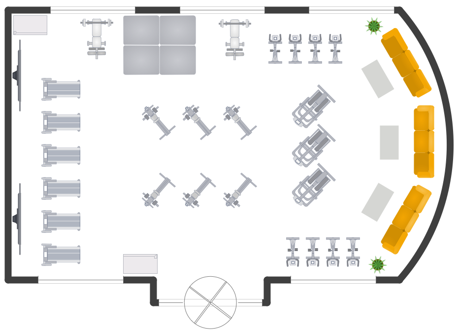
Cafe is a perfect place for business meetings, romantic rendezvous, friendly leisures, both adults and children, it is a popular place of relaxation and recreation, staying in which delivers many lively emotions, impressions and memories. Therefore, the opening of the adult or children's cafe, Internet cafe, elite or even thematic cafe is a fine business idea. At the same time when opening a cafe, you need consider a number of nuances and undertake important steps - to make a business plan, choose a popular location, create interesting and comfort cafe interior style and design, draw detailed Cafe floor plan, construct the catchy building if it was not built yet, and make the repairs. On these stages you can enlist the help of professionals, architects and designers, either make themselves your own professional-looking Cafe Floor Plans using the ConceptDraw DIAGRAM software.
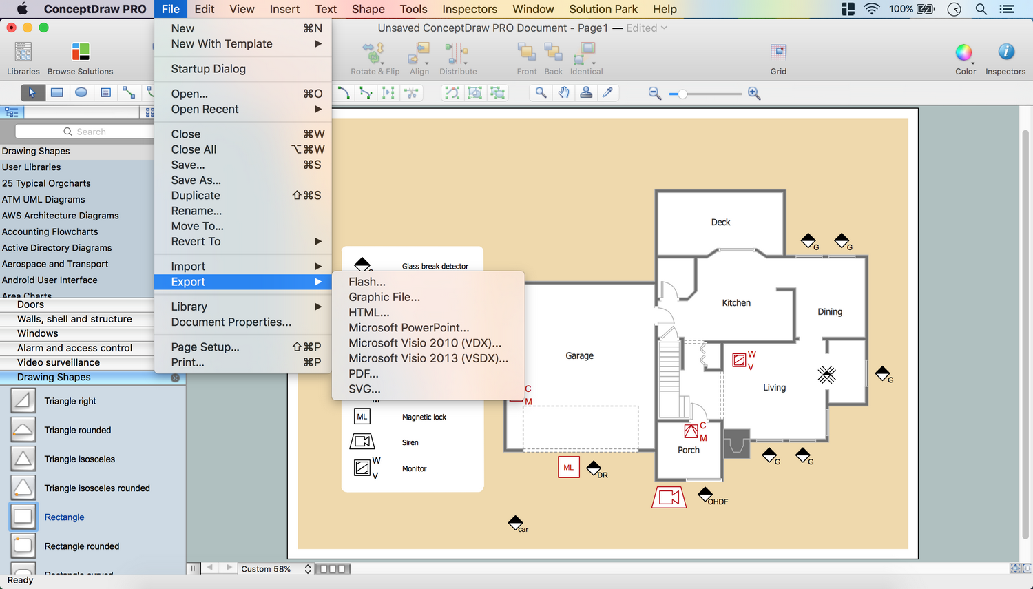
Quick start with ready predesigned Cafe floor plans templates, examples or samples, ready-to-use vector symbols that make you instantly productive in drawing Cafe Floor Plans, Cafe Layouts, Cafe Design Plans.
_Win_Mac.png)