Structured Systems Analysis and Design Method. SSADM with ConceptDraw DIAGRAM

Data Flow Diagram

UML Use Case Diagram Example. Registration System

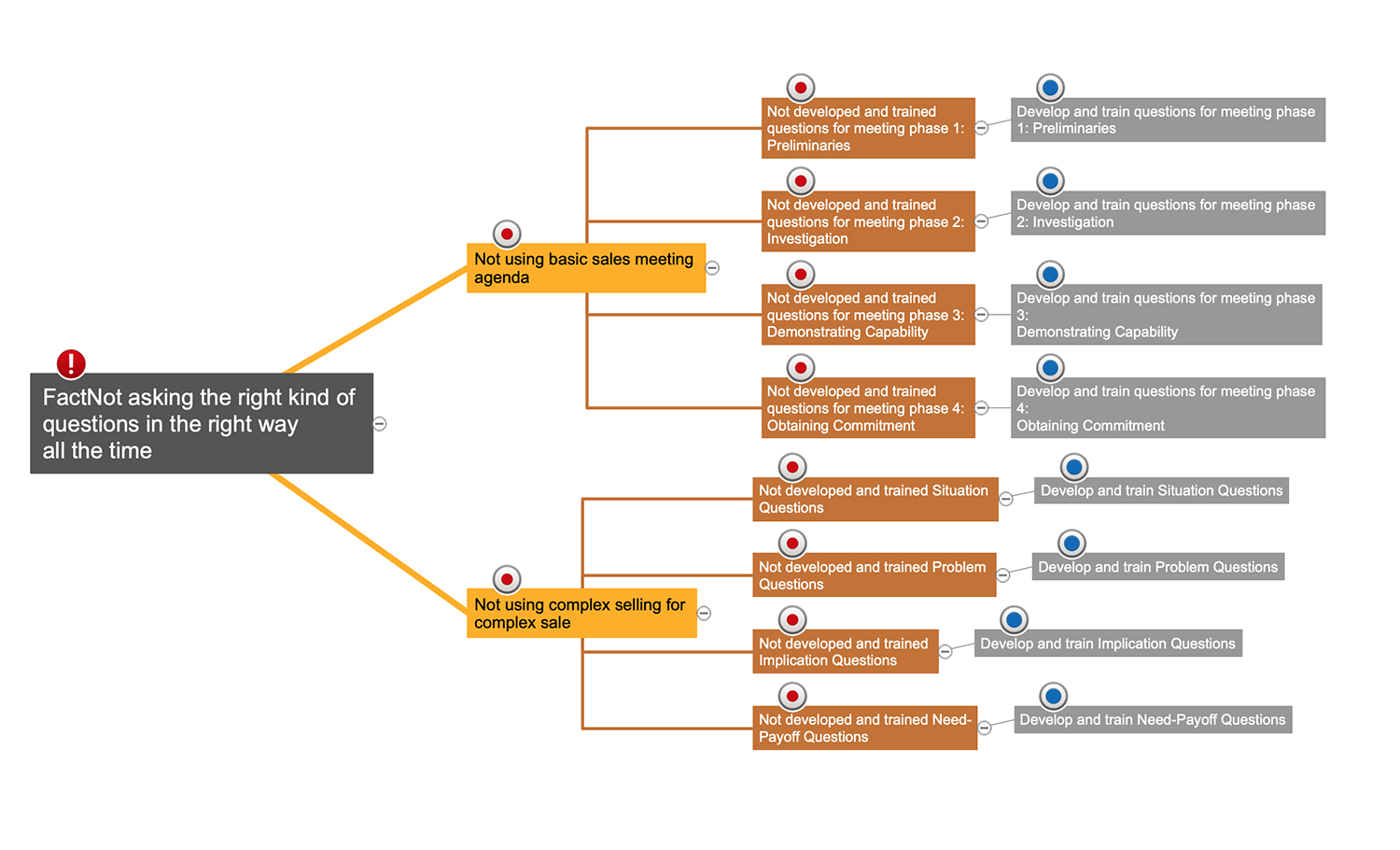
Cause and Effect Analysis

Pyramid Diagram

Flowchart
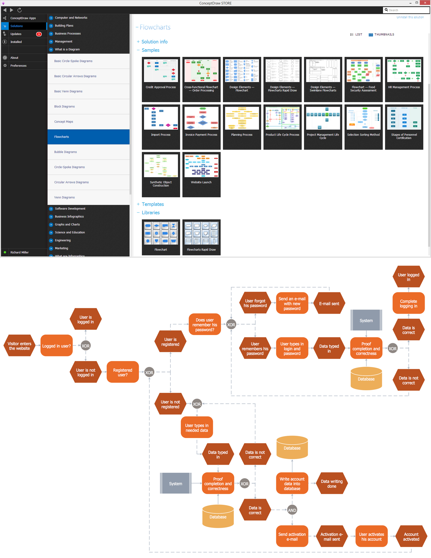
TQM Diagram — Professional Total Quality Management
Example of DFD for Online Store (Data Flow Diagram)


 Event-driven Process Chain Diagrams
Event-Driven Process Chain Diagrams solution extends ConceptDraw DIAGRAM functionality with event driven process chain templates, samples of EPC engineering and modeling the business processes, and a vector shape library for drawing the EPC diagrams and EPC flowcharts of any complexity. It is one of EPC IT solutions that assist the marketing experts, business specialists, engineers, educators and researchers in resources planning and improving the business processes using the EPC flowchart or EPC diagram. Use the EPC solutions tools to construct the chain of events and functions, to illustrate the structure of a business process control flow, to describe people and tasks for execution the business processes, to identify the inefficient businesses processes and measures required to make them efficient.
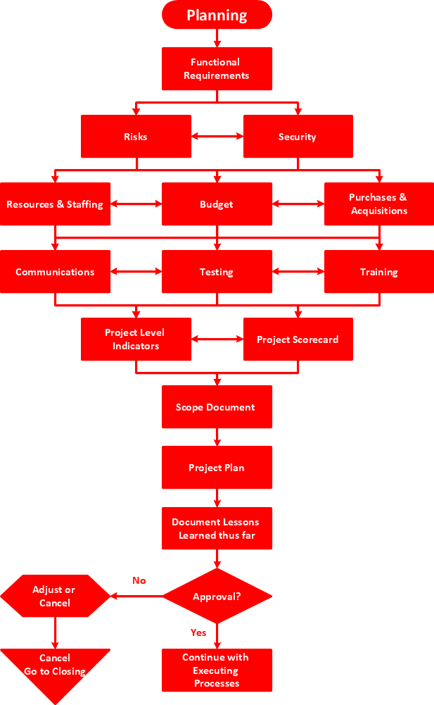
Sales Process Flowchart. Flowchart Examples

- Analysis For Procedure Of Registration Of Partnership Firm
- Registration For Partnership Firm Analysis Data Com
- Analysis On Registration On Partnership Firm
- Partnership Firm Process And Procedure Analysis Of Data Wiki
- SWOT Analysis | Registration Of Partnership Diagrams
- Analaysis Data Of Registration Of Partnership Firm
- Partnership Firm Process And Procedure Analysis Of Data
- Partnership Firm Process And Procedure Presentation Of Data And ...
- Methodology Of Process And Procedure Of Partnership Firm