Basic Flowchart Symbols and Meaning


, t chart, decision matrix, decision tree analysis") Decision Making
Decision Making
The Decision Making solution offers the set of professionally developed examples, powerful drawing tools and a wide range of libraries with specific ready-made vector decision icons, decision pictograms, decision flowchart elements, decision tree icons, decision signs arrows, and callouts, allowing the decision maker (even without drawing and design skills) to easily construct Decision diagrams, Business decision maps, Decision flowcharts, Decision trees, Decision matrix, T Chart, Influence diagrams, which are powerful in questions of decision making, holding decision tree analysis and Analytic Hierarchy Process (AHP), visual decomposition the decision problem into hierarchy of easily comprehensible sub-problems and solving them without any efforts.
Basic Flowchart Examples
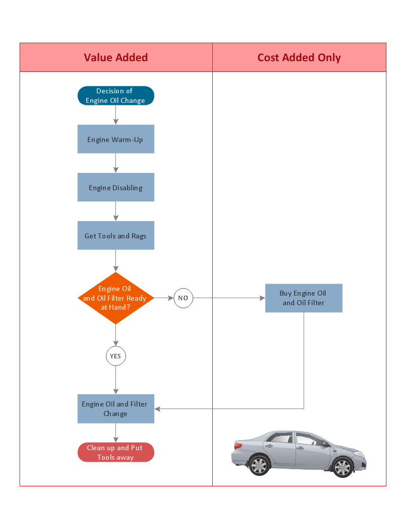
Electrical Symbols, Electrical Diagram Symbols

Entity Relationship Diagram Symbols

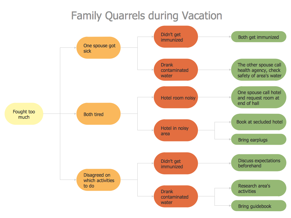
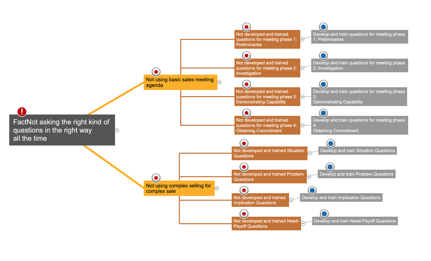
Problem solving

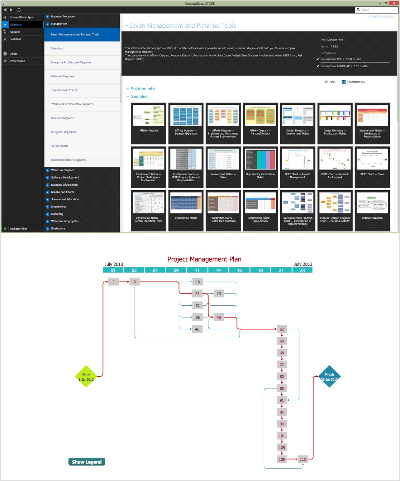
 Seven Management and Planning Tools
Seven Management and Planning Tools solution extends ConceptDraw DIAGRAM and ConceptDraw MINDMAP with features, templates, samples and libraries of vector stencils for drawing management mind maps and diagrams.
CORRECTIVE ACTIONS PLANNING. PERT Chart
Total Quality Management Business Diagram
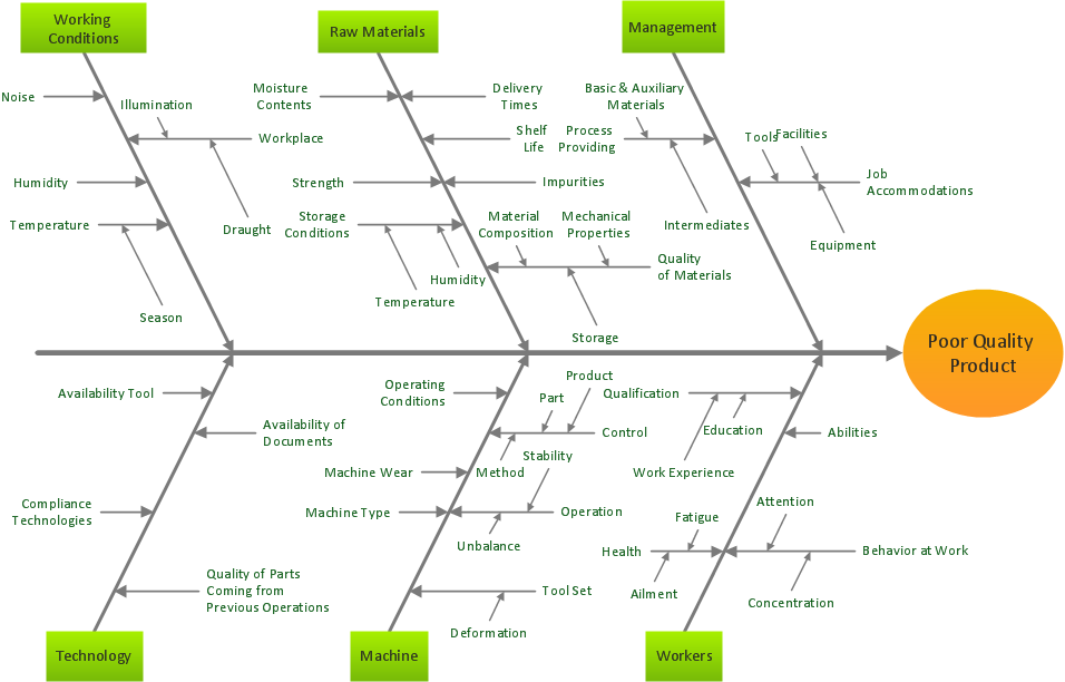
Cause and Effect Analysis
- Network Diagram Software Backbone Network | Identify Parts Of A ...
- PROBLEM ANALYSIS. Prioritization Matrix | Cause and Effect ...
- Problem Analysis Matrix Definition
- Seven Management and Planning Tools | PROBLEM ANALYSIS ...
- Cisco People. Cisco icons , shapes, stencils and symbols | Person ...
- 7 Management & Planning Tools | Seven Management and ...
- Relations diagram - Template | PROBLEM ANALYSIS. Relations ...
- Using Fishbone Diagrams for Problem Solving | SWOT Analysis ...
- Fishbone diagram - Bad coffee | Ishikawa Diagram | SWOT Analysis ...
- How to Manage Problem Solving Using Seven Management and ...