Piping and Instrumentation Diagram Software

Building Drawing. Design Element: Piping Plan


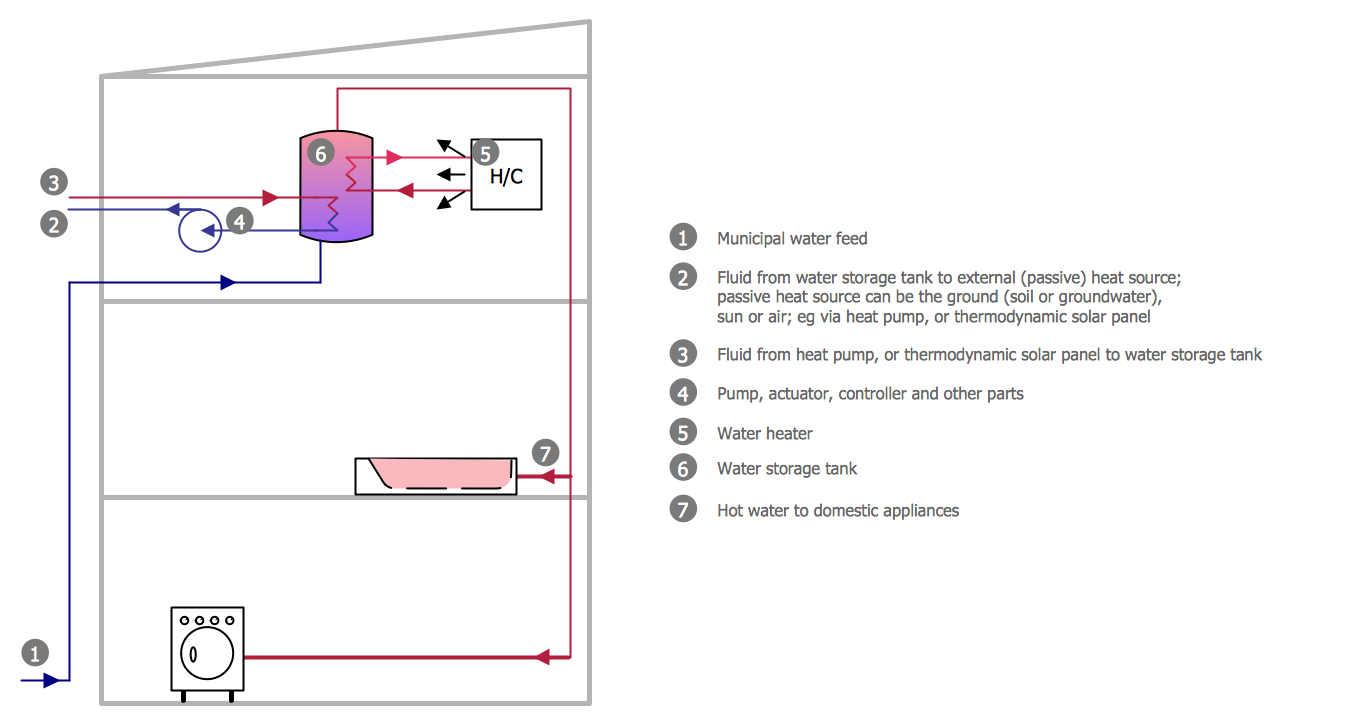
 Plumbing and Piping Plans
Plumbing and Piping Plans solution extends ConceptDraw DIAGRAM.2.2 software with samples, templates and libraries of pipes, plumbing, and valves design elements for developing of water and plumbing systems, and for drawing Plumbing plan, Piping plan, PVC Pipe plan, PVC Pipe furniture plan, Plumbing layout plan, Plumbing floor plan, Half pipe plans, Pipe bender plans.
Interior Design. Piping Plan — Design Elements

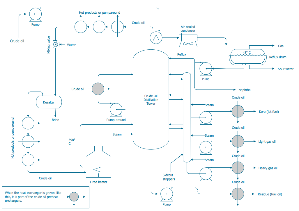
"A piping and instrumentation diagram/ drawing (P&ID) is a diagram in the process industry which shows the piping of the process flow together with the installed equipment and instrumentation. ...
P&IDs play a significant role in the maintenance and modification of the process that it describes. It is critical to demonstrate the physical sequence of equipment and systems, as well as how these systems connect. During the design stage, the diagram also provides the basis for the development of system control schemes, allowing for further safety and operational investigations, such as a Hazard Analysis and Operability Study...
For processing facilities, it is a pictorial representation of:
Key piping and instrument details,
Control and shutdown schemes,
Safety and regulatory requirements,
Basic start up and operational information." [Piping and instrumentation diagram. Wikipedia]
The piping and instrumentation diagram template for the ConceptDraw PRO diagramming and vector drawing software is included in the Chemical and Process Engineering solution from the Engineering area of ConceptDraw Solution Park.
Piping and instrumentation diagram / drawing (P&ID)
-piping-and-instrumentation-diagram-template.png--diagram-flowchart-example.png)
Building Drawing Software for Design Piping Plan
Process and Instrumentation Diagram
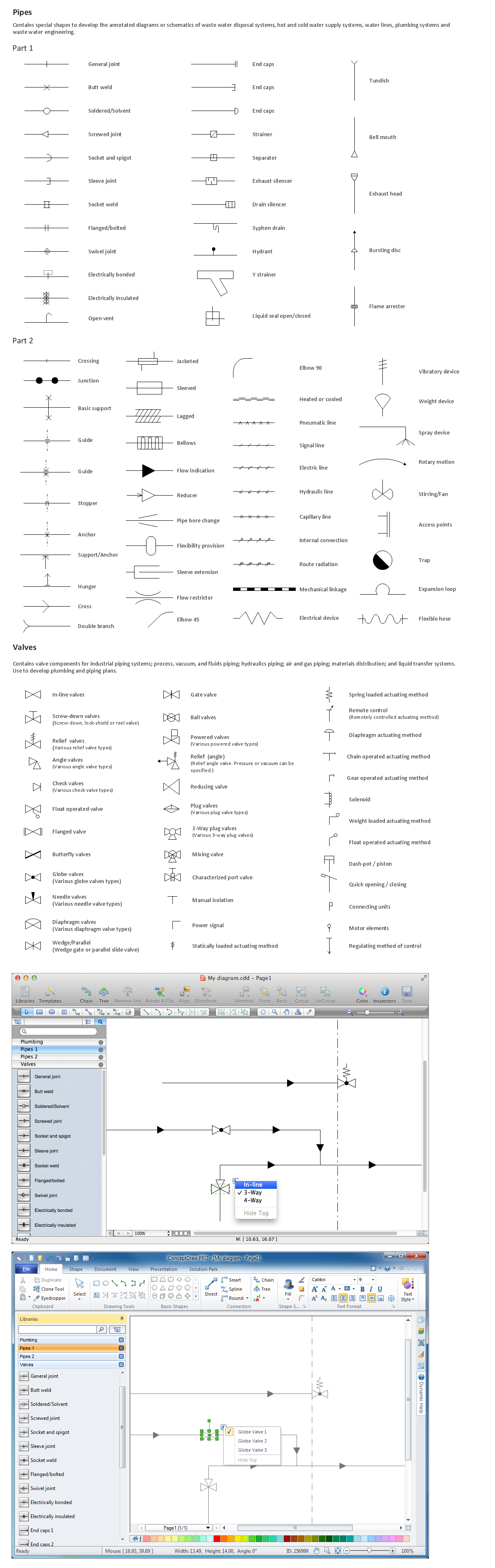
The vector stencils libraries "Pipes 1" and "Pipes 2" contain 28 and 48 pipe, tubing and fitting symbols, respectively.
"A fitting is used in pipe plumbing systems to connect straight pipe or tubing sections, to adapt to different sizes or shapes, and for other purposes, such as regulating or measuring fluid flow. The term plumbing is generally used to describe conveyance of water, gas, or liquid waste in ordinary domestic or commercial environments, whereas piping is often used to describe high-performance (e.g. high pressure, high flow, high temperature, hazardous materials) conveyance of fluids in specialized applications. The term tubing is sometimes used for lighter-weight piping, especially types that are flexible enough to be supplied in coiled form.
Fittings (especially uncommon types) require money, time, materials, and tools to install, so they are a non-trivial part of piping and plumbing systems." [Piping and plumbing fitting. Wikipedia]
Use the design elements libraries "Pipes 1" and "Pipes 2" for drawing plumbing and piping building plans, schematic diagrams, blueprints, or technical drawings of waste water disposal systems, hot and cold water supply systems using the ConceptDraw PRO diagramming and vector drawing software.
The shapes libraries "Pipes 1" and "Pipes 2" are contained in the Plumbing and Piping Plans solution from the Building Plans area of ConceptDraw Solution Park.
Piping symbols
.png--diagram-flowchart-example.png)
Half Pipe Plans
The vector stencils libraries "Pipes 1" and "Pipes 2" contain 28 and 48 pipe, tubing and fitting symbols, respectively.
"Pipe is hollow cylinder used to conduct or transfer fluids (liquids and gases) from one place to other place. The main difference between pipe and tube is the critical dimension used to describe the pipe size or the tube size. For pipe, internal diameter (ID) roughly corresponds to the nominal pipe size for standard wall thickness. For tube, the outer diameter (OD) closely corresponds to the tube size. In current European standards pipes and tubes are nowadays described as outside diameter by wall thickness. The three standard types of pipe ends used in the piping industriesare; Plain Ends (PE), Threaded Ends (TE) and Beveled Ends (BE). In the past, many types of material have been used in conveying water from one point to another. Masonry and wood were probably the first materials used. Plastics are the newest, and are now being used quite extensively." [Piping. Wikipedia]
Use the design elements libraries "Pipes 1" and "Pipes 2" for drawing plumbing and piping building plans, schematic diagrams, blueprints, or technical drawings of waste water disposal systems, hot and cold water supply systems using the ConceptDraw PRO diagramming and vector drawing software.
The shapes libraries "Pipes 1" and "Pipes 2" are contained in the Plumbing and Piping Plans solution from the Building Plans area of ConceptDraw Solution Park.
Piping symbols
.png--diagram-flowchart-example.png)
- Plumbing and Piping Plans | Bilding Pipe Droing
- How to Create a Residential Plumbing Plan | Piping Symbols In ...
- Plumbing and Piping Plans | How to Create a Residential Plumbing ...
- Plumbing and Piping Plans | House plumbing plan | How to Create a ...
- Plumbing and Piping Plans | House Wiring Piping Solution
- Plumbing and Piping Plans | Flat plumbing plan | Plumbing - Vector ...
- Plumbing and Piping Plans | Mechanical Engineering | Piping Plan ...
- Welding symbols | Plumbing and Piping Plans | Design elements ...
- Plumbing and Piping Plans | Half Pipe Plans | Pipe Bender Plans ...
- Plant Layout Plans | Plumbing and Piping Plans | Piping Design ...