This site uses cookies. By continuing to browse the ConceptDraw site you are agreeing to our Use of Site Cookies.

Piping and Instrumentation Diagram Software

Piping and Instrumentation Diagram is a technical sketch or drawing, which shows in details the piping system and instrumentation of a processing plant. Piping and Instrumentation Diagram is developed by process design engineers and technical engineers on the phase of plant design. This plan is necessary on the stages of plant construction and then is actively used by operators, instrumentation and piping engineers when operating the plant. ConceptDraw DIAGRAM software provides unique Plumbing and Piping Plans solution from Building Plans area of ConceptDraw Solution Park with 10 libraries of ready-to-use predesigned vector elements, templates and samples, to help you create professional Piping diagrams and schematics, Instrumentation diagrams, Plumbing plans and blueprints, Schemes of hot and cold water supply systems, Heating schemes, Mechanical diagrams, Diagrams of fluids, hydraulics, air and gas pipings, Technical drawings of waste water disposal systems, Schematics of industrial piping systems, Diagrams of ventilation systems, etc.

How To use House Electrical Plan Software

How we can conduct the electricity at house correctly without a plan? It is impossible. The House electrical diagram depicts locations of switches, outlets, dimmers and lights, and lets understand how you will connect them. But design of House Electrical Plan looks a complex task at a glance, which requires a lot of tools and special experience. But now all is simple with all-inclusive floor plan software - ConceptDraw DIAGRAM. As a house electrical plan software, the ConceptDraw DIAGRAM contains libraries with a large range of professional lighting and electrical symbols, ready-to-use electrical plans samples and examples, and built-in templates for creating great-looking Home floor electrical plans. It is a fastest way to draw Electrical circuit diagrams, Electrical wiring and Circuit schematics, Digital circuits, Electrical equipment, House electrical plans, Satellite television, Cable television, Home cinema, Closed-circuit television when are used the tools of Electric and Telecom Plans Solution from ConceptDraw Solution Park. Files created in Visio for Mac app can be easily imported to ConceptDraw DIAGRAM. Also you may import stencils and even libraries. Try for free an alternative to Visio that Apple users recommend.
Create an Electrical Diagram

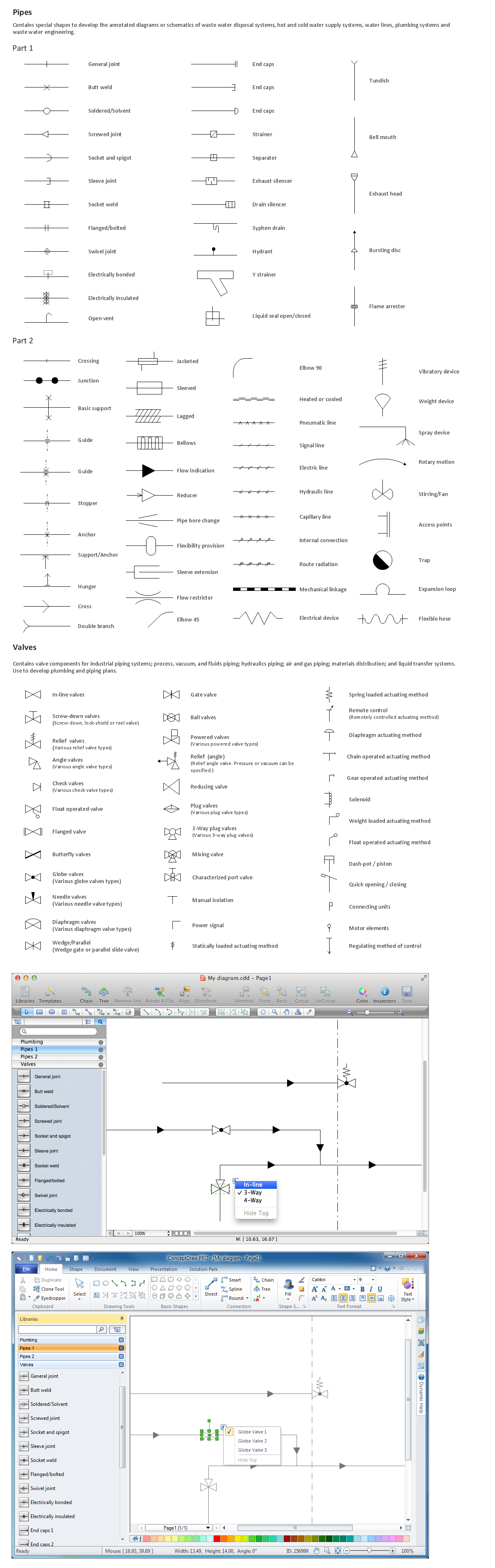
Building Drawing Software for Designing Plumbing

The construction project for any building obligatory must include the plans for systems of water supplying, sewerage, lighting and heating. From one side these are the documents required and indispensable for the construction, but from the other side this is a way of correct and effective selection of equipment, and subsequent its installation. Correctly performed calculations for these systems ensure a reliable, energy-efficient and cost-effective work. At this each project is fully individual decision taking into account all nuances - from the features of building to the personal preferences. ConceptDraw DIAGRAM is a powerful building drawing software for designing Plumbing, Piping, Lighting and other building plans thanks to the included Plumbing and Piping Plans solution and other solutions from Building Plans area. Plumbing and Piping Plans solution includes variety of libraries with different design elements of pipes, valves and other sanitary equipment and helps easy develop the annotated schematics and diagrams of plumbing systems, piping, and waste water.

pvc pipe furniture plans, pvc pipe plans, plumbing plans examples, How to read plumbing plans? plumbing floor plan, plumbing layout plan, half pipe plans, pipe bender plans, plumbing plan symbols Plumbing and Piping Plans

pvc pipe furniture plans, pvc pipe plans, plumbing plans examples, How to read plumbing plans? plumbing floor plan, plumbing layout plan, half pipe plans, pipe bender plans, plumbing plan symbols
Plumbing and Piping Plans solution extends ConceptDraw DIAGRAM.2.2 software with samples, templates and libraries of pipes, plumbing, and valves design elements for developing of water and plumbing systems, and for drawing Plumbing plan, Piping plan, PVC Pipe plan, PVC Pipe furniture plan, Plumbing layout plan, Plumbing floor plan, Half pipe plans, Pipe bender plans.

Building Drawing. Design Element: Piping Plan

When you are going to build a house or to make repairs of new built home, apartment, office, shop, or to renovate any other premises, in many cases you will need to make the package of drawings, plans and documents, including the such important plans as the Overall floor plan, Interior design plan, Ceiling plan, Electrical system plan, and of course the Plumbing plan, Water supply system plan, and Piping Plan. When choosing between the modern software for building construction, planning and design, we recommend you to select the multifunctional building plan software ConceptDraw DIAGRAM enhanced with Plumbing and Piping Plans solution from the Building Plans area of ConceptDraw Solution Park. This solution provides large variety of examples, samples, quick-start templates and libraries of pipes, plumbing and valves vector design elements for design and construction the Plumbing and Piping Plans, schematics and annotated diagrams for hot and cold water supply systems, water lines and waste water disposal systems.
This HVAC schematics sample depicts the house cool mode of central air pool heater. It was drawn on the base of the HVAC schematics in the post "Central Air Pool Heater" from the Nathan Stratton's blog.
"With House Cool Mode, hot gas leaves the compressor runs through the reversing value into the condenser where it condenses into a liquid. Valve #1 is ON so liquid is able to leave the outside unit and run through the filter dryer and site glass into the evaporator upstairs in the house where the liquid flashes into a gas as it passes through the expansion valve and absorbs heat from the air passing through the evaporator. The cold gas travels downstairs and outside to the compressor and the cycle starts all over again." [robotics.net/ projects/ central-air-pool-heater/ ]
The HVAC schematics example "Central air pool heater" was created using the ConceptDraw DIAGRAM diagramming and vector drawing software extended with the HVAC Plans solution from the Building Plans area of ConceptDraw Solution Park.
HVAC schematics
HVAC schematics, water flow meter, return duct, propeller fan, pipe flow arrow, pipe coil, air filter,

Process Flowchart

The main reason of using Process Flowchart or PFD is to show relations between major parts of the system. Process Flowcharts are used in process engineering and chemical industry where there is a requirement of depicting relationships between major components only and not include minor parts. Process Flowcharts for single unit or multiple units differ in their structure and implementation. ConceptDraw DIAGRAM is Professional business process mapping software for making Process flowcharts, Process flow diagram, Workflow diagram, flowcharts and technical illustrations for business documents and also comprehensive visio for mac application. Easier define and document basic work and data flows, financial, production and quality management processes to increase efficiency of your business with ConcepDraw DIAGRAM. Business process mapping software with Flowchart Maker ConceptDraw DIAGRAM includes extensive drawing tools, rich examples and templates, process flowchart symbols and shape libraries, smart connectors that allow you create the flowcharts of complex processes, process flow diagrams, procedures and information exchange. Process Flowchart Solution is project management workflow tools which is part ConceptDraw Project marketing project management software. Drawing charts, diagrams, and network layouts has long been the monopoly of Microsoft Visio, making Mac users to struggle when needing such visio alternative like visio for mac, it requires only to view features, make a minor edit to, or print a diagram or chart. Thankfully to MS Visio alternative like ConceptDraw DIAGRAM software, this is cross-platform charting and business process management tool, now visio alternative for making sort of visio diagram is not a problem anymore however many people still name it business process visio tools.
How To Create a Process Flow Chart (business process modelling techniques)

Building Drawing Software for Design Piping Plan

Use building drawing software to develop the annotated diagrams or schematics of waste water disposal systems, hot and cold water supply systems, water lines and waste water engineering.

Building Drawing. Design Element — Plumbing

Any repair or replanning usually requires a work with engineering communications and sanitary equipment. This can be the new system's construction or the dismantling of old pipes and plumbing, and then installation the new ones. The reliability of plumbing system depends on many factors, but in any case, a prerequisite is careful planning, competent and qualified project's development, design of necessary Plumbing diagrams, creation the plan of plumbing works, high-quality laying of pipes and correct installation of engineering communications, plumbing and sanitary equipment according to the developed schemes. The key point at the development schemes and plans is the necessity to clearly think over all required plumbing equipment, to choose the types of pipes, a way of montage and to count their quantity. ConceptDraw DIAGRAM software extended with Plumbing and Piping Plans solution is the ease way to create professional-looking Plumbing plans, Piping plans, Water supply system plans, Plumbing system layout plans, thanks to the included plumbing and piping vector design elements.

Interior Design. Plumbing — Design Elements

The plumbing system is a complex system of water supply pipes and drainpipes, sanitary equipment and drainage facilities, vent pipes and more. It supplies our homes, offices, hospitals, schools, business centers, and many other buildings with the main product for life - a water. For effective planning and montage the plumbing equipment, you need obligatory create and use different schematics of plumbing systems, the annotated plumbing diagrams, water lines and waste water plans. These diagrams are an obligatory part of any building project. They are used at all stages - construction, finishing works, interior design, and also during the exploitation of premises in cases of occurence some problems. Numerous libraries offered by the Plumbing and Piping Plans solution from Building Plans area of ConceptDraw Solution Park contain vector objects of plumbing components, sanitary equipment, bathroom fixtures, and many more for easy design the Plumbing and Piping plans, schematic diagrams and blueprints for hot and cold water supply systems, and waste water disposal systems.