Process Flow Diagram Symbols

Process Engineering

Accounting Flowchart Symbols

The vector stencils library "Industrial equipment" contains 81 symbols of pumps, compressors, fans, turbines, and power generators.
Use these shapes to design pumping systems, air and fluid compression systems, and industrial process diagrams.
"Process engineering focuses on the design, operation, control, and optimization of chemical, physical, and biological processes. Process engineering encompasses a vast range of industries, such as chemical, petrochemical, mineral processing, advanced material, food, pharmaceutical, and biotechnological industries. The application of systematic computer-based methods to process engineering is process systems engineering." [Process engineering. Wikipedia]
The example "Design elements - Industrial equipment" was created using the ConceptDraw PRO diagramming and vector drawing software extended with the Chemical and Process Engineering solution from the Engineering area of ConceptDraw Solution Park.
Industrial equipment symbols

The vector stencils library "Fault tree analysis diagrams" contains 12 symbols for drawing Fault Tree Analysis (FTA) diagrams.
"Fault tree analysis (FTA) is a top down, deductive failure analysis in which an undesired state of a system is analyzed using Boolean logic to combine a series of lower-level events. This analysis method is mainly used in the fields of safety engineering and reliability engineering to understand how systems can fail, to identify the best ways to reduce risk or to determine (or get a feeling for) event rates of a safety accident or a particular system level (functional) failure. FTA is used in the aerospace, nuclear power, chemical and process, pharmaceutical, petrochemical and other high-hazard industries; but is also used in fields as diverse as risk factor identification relating to social service system failure.
In aerospace, the more general term "system Failure Condition" is used for the "undesired state" / Top event of the fault tree. These conditions are classified by the severity of their effects. The most severe conditions require the most extensive fault tree analysis. These "system Failure Conditions" and their classification are often previously determined in the functional Hazard analysis." [Fault tree analysis. Wikipedia]
The shapes example "Fault tree analysis diagrams" was created using the ConceptDraw PRO diagramming and vector drawing software extended with the Fault Tree Analysis Diagrams solution from the Engineering area of ConceptDraw Solution Park.
FTA diagram symbols

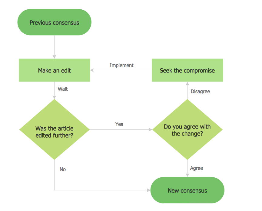
Software Work Flow Process in Project Management with Diagram

This sample shows the Workflow Diagram that clearly illustrates stages a BPM consists of and relations between all parts of business. The Workflow Diagrams are used to represent the transferring of data during the work process, to study and analysis the working processes, and to optimize a workflow.
CAD Software for Architectural Designs
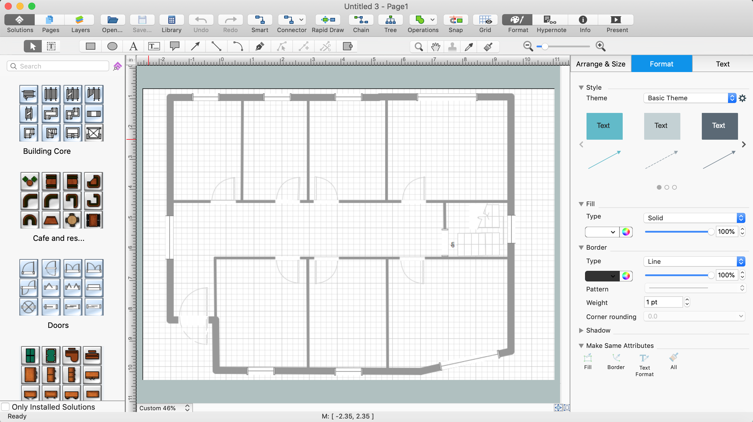
Use the libraries with a set of vector objects, templates and samples from the Floor Plans Solution from the Building Plans area of ConceptDraw Solution Park for designing your professional architectural designs.
Fault Tree Analysis Software

Process Flow Diagram

Process Flow Chart

Flow Chart Online

Example Basic Flowchart. Flowchart Examples
- Process Engineering | Process Flow Diagram Symbols | Chemical ...
- Process Engineering | Process Flow Diagram Symbols | Design ...
- Process Engineering | Amine treating unit schematic diagram ...
- Process Engineering | Process Flow Diagram Symbols | Process ...
- Petrochemical Industry Wih Help Of Process Flow Diagram
- Petrochemical Process Flow Chart
- Process Flow Diagram | Process Diagrams | Petrochemical Unit ...
- Unit Operation Used In Petrochemical Industry With Help Of Process
- Process Flow Diagram Symbols | CAD Software for Architectural ...
- Petrochemical Refinery Flow Chart
- Process Flow Diagram Symbols | Process Flowchart | Design ...
- Process Flow Diagram Symbols | Petroleum products yielded from ...
- Process Flow Diagram Symbols | Mechanical Drawing Symbols ...
- Diagrams To Show Unit Operations In Petroleum Engineering
- Process Flow Diagram Symbols | Chemical Engineering | How to ...
- Process Flow Diagram Symbols | Process Flowchart | Chemical and ...
- Design elements - Pumps | Process Flow Diagram Symbols | Piping ...
- Piping and Instrumentation Diagram Software | Process Engineering ...
- Process Flow Diagram Symbols | Process Flow Diagram | Energy ...
- Symbols Used In Pharmaceutical Engineering