 ATM UML Diagrams
The ATM UML Diagrams solution lets you create ATM solutions and UML examples. Use ConceptDraw DIAGRAM as a UML diagram creator to visualize a banking system.
HelpDesk
How to Create a Bank ATM Use Case Diagram

 Object-Role Modeling (ORM) Diagrams
Object-role Modeling (ORM) Diagram solution with powerful vector diagramming and data modeling tools, large quantity of specially developed samples and examples, and rich variety of vector objects corresponding to common ORM notation, ideally suits for developing the comprehensive, clear and visual Object-role Modeling (ORM) diagrams and schematics, understandable for all interested people from the different fields and business directions, for designing the ORM models, and demonstrating advantages from the use of ORM and its notation. It is intended for software developers and computer engineers, specialists in a field of Object-oriented programming (OOP), database architects, web-application constructors and developers, etc.
UML Software

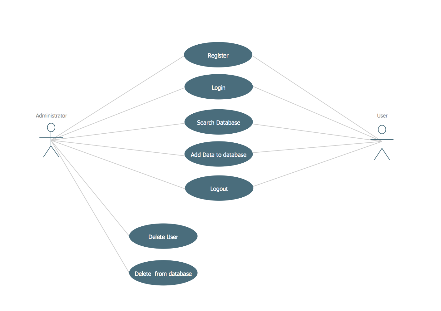
UML Use Case Diagram Example Registration System
UML Package Diagram. Design Elements

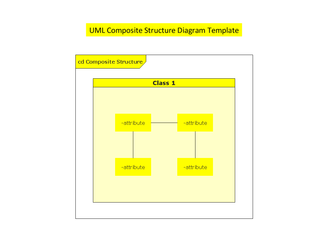
UML Composite Structure Diagram

OMT Method

UML Diagram

UML Diagram Types List

- Drwa A Sample Object Model Of Atm Machine
- ATM UML Diagrams | Databases Access Objects Model with ...
- ATM UML Diagrams | Business Process Diagrams | How to Create a ...
- Object Modeling Diagram Of Atm
- How to Create a Bank ATM Use Case Diagram | ATM UML ...
- Coad/Yourdon's Object -Oriented Analysis model | ATM UML ...
- Fsm State Machine Model Of An Atm System
- Coad/Yourdon's Object -Oriented Analysis model | Data Flow ...
- Draw And Explain Object Diagram For Your Atm System
- Uml Atm