Network Diagram Software. LAN Network Diagrams. Physical Office Network Diagrams
ConceptDraw Network Diagramming Software with examples of WAN, LAN Diagrams. ConceptDraw Network Diagram is ideal for network engineers and network designers who need to draw Local Area Network diagrams, physical office network diagrams and Diagram for LAN.Physical Security Plan
ConceptDraw DIAGRAM diagramming and vector drawing software extended with Security and Access Plans Solution from the Building Plans Area of ConceptDraw Solution Park is a powerful software for fast and easy drawing professional looking Physical Security Plan.Electrical and Telecom Plan Software
ConceptDraw is a fast way to draw: Electrical circuit diagrams, Electrical wiring diagrams, Telecom plans, Schematics, House electrical plans, Control wiring diagrams, Power-riser diagrams, Cabling layout schemes, Reflected ceiling plans, Lighting panels layouts.Wiring Diagrams with ConceptDraw DIAGRAM
A wiring diagram is a comprehensive diagram of each electrical circuit system showing all the connectors, wiring, terminal boards, signal connections (buses) between the devices and electrical or electronic components of the circuit. It also identifies the wires by wire numbers or colour coding. Wiring diagrams are necessary to troubleshoot and fix electrical or electronic circuits.
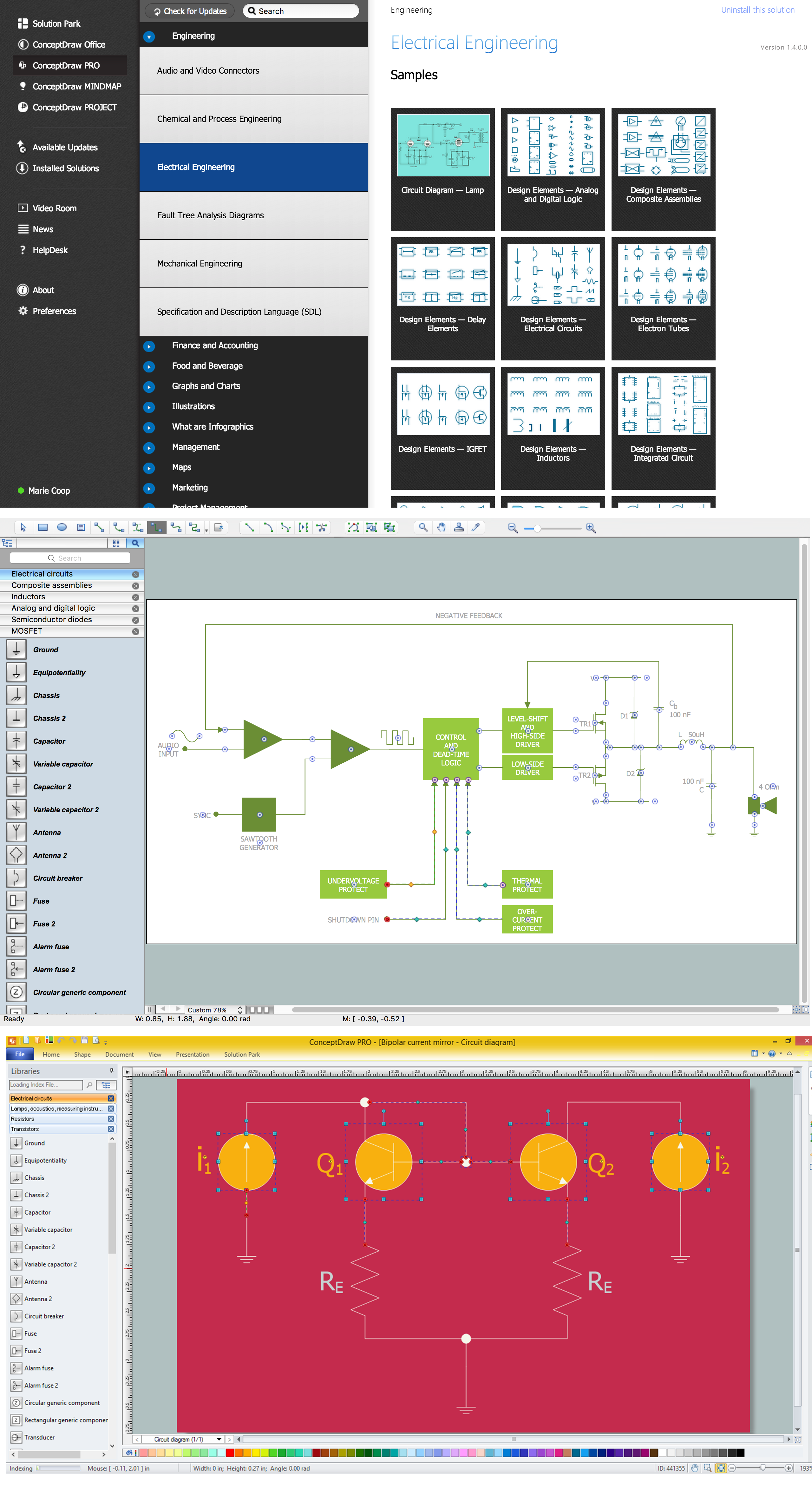
Electrical Symbols, Electrical Diagram Symbols
How to create Electrical Diagram? It’s very easy! All you need is a powerful software. It wasn’t so easy to create Electrical Symbols and Electrical Diagram as it is now with electrical diagram symbols offered by the libraries of Electrical Engineering Solution from the Industrial Engineering Area at the ConceptDraw Solution Park.This solution provides 26 libraries which contain 926 electrical symbols from electrical engineering: Analog and Digital Logic, Composite Assemblies, Delay Elements, Electrical Circuits, Electron Tubes, IGFET, Inductors, Integrated Circuit, Lamps, Acoustics, Readouts, Logic Gate Diagram, MOSFET, Maintenance, Power Sources, Qualifying, Resistors, Rotating Equipment, Semiconductor Diodes, Semiconductors, Stations, Switches and Relays, Terminals and Connectors, Thermo, Transformers and Windings, Transistors, Transmission Paths,VHF UHF SHF.
HelpDesk
How to Create a CCTV Diagram
CCTV (Closed-circuit television) diagram is used to depict a system of video monitoring. The CCTV diagram provides video cameras placement strategy.CCTV diagram should include the scheme of strategic placement of video cameras, which capture and transmit videos to either a private network of monitors for real-time viewing or to a video recorder for later reference. CCTV is commonly used for surveillance and security purposes. Using ConceptDraw DIAGRAM with the Security and Access Plans Solution lets you create professional looking video surveillance CCTV system plans, security plans, and access schemes.
Making Mechanical Diagram
The engineering diagrams produced with ConceptDraw DIAGRAM are vector graphic documents and are available for reviewing, modifying, and converting to a variety of formats (image, HTML, PDF file, MS PowerPoint Presentation, Adobe Flash or MS Visio XML).CAD Drawing Software for Making Mechanic Diagram and Electrical Diagram Architectural Designs
CAD (Computer-aided design) software is used for improvement the quality of design and the productivity of the designer, for creating the database for manufacturing. Computer-aided design is used in many fields: in mechanical and industrial design, in designing electronic systems and electrical diagrams for architectural design, in automotive, aerospace, shipbuilding industries.UML Class Diagram Example for GoodsTransportation System
Class Diagram for Goods Transport System in UML. This sample was created in ConceptDraw DIAGRAM diagramming and vector drawing software using the UML Class Diagram library of the Rapid UML Solution from the Software Development area of ConceptDraw Solution Park.This sample shows the concept of working of the transport company and is used by transport companies, carriers at the transportation of various goods.
ATM UML Diagrams
The ATM UML Diagrams solution lets you create ATM solutions and UML examples. Use ConceptDraw DIAGRAM as a UML diagram creator to visualize a banking system.
- Design Element: IVR for Network Diagrams | Riser Diagram ...
- Design Element: IVR for Network Diagrams | Cable TV - Vector ...
- Riser Diagram Combination
- Design Element: IVR for Network Diagrams | Design elements ...
- Telecommunication Riser Diagram Autocad Drawings
- Telecommunication Risers Diagram Cadd Drawings
- Network Layout Floor Plans | Network Diagram Software LAN ...
- Basic CCTV System Diagram . CCTV Network Diagram Example ...
- Computer System Riser Diagram
- Standard Telephone Riser Diagram
- ERD | Entity Relationship Diagrams, ERD Software for Mac and Win
- Flowchart | Basic Flowchart Symbols and Meaning
- Flowchart | Flowchart Design - Symbols, Shapes, Stencils and Icons
- Flowchart | Flow Chart Symbols
- Electrical | Electrical Drawing - Wiring and Circuits Schematics
- Flowchart | Common Flowchart Symbols