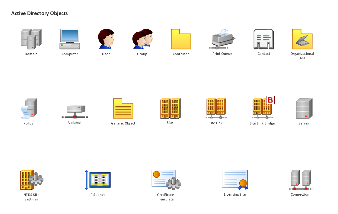
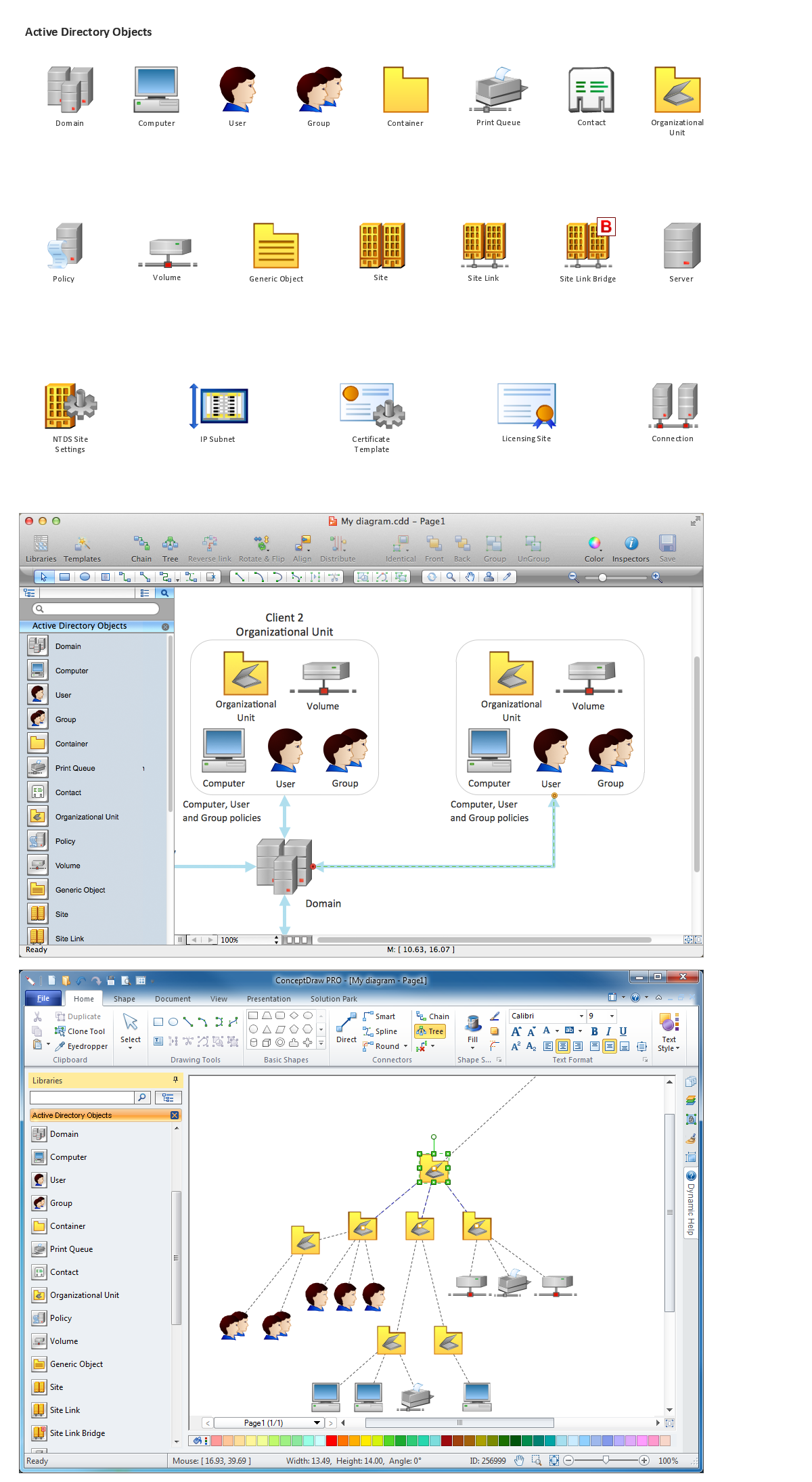
Design Element: Active Directory for Network Diagrams

HelpDesk
How to Add a Telecommunication Network Diagram to a PowerPoint Presentation

"A telecommunications network is a collection of terminal nodes, links and any intermediate nodes which are connected so as to enable telecommunication between the terminals. The transmission links connect the nodes together. The nodes use circuit switching, message switching or packet switching to pass the signal through the correct links and nodes to reach the correct destination terminal. Each terminal in the network usually has a unique address so messages or connections can be routed to the correct recipients. The collection of addresses in the network is called the address space. Examples of telecommunications networks are: computer networks, Internet, telephone network, global Telex network, aeronautical ACARS network." [Telecommunications network. Wikipedia]
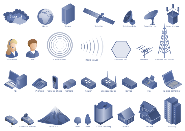
The example "Design elements - Telecommunication networks" was created using the ConceptDraw PRO diagramming and vector drawing software extended with the Telecommunication Network Diagrams solution from the Computer and Networks area of ConceptDraw Solution Park.
The example "Design elements - Telecommunication networks" was created using the ConceptDraw PRO diagramming and vector drawing software extended with the Telecommunication Network Diagrams solution from the Computer and Networks area of ConceptDraw Solution Park.
Telecom diagram symbols
The vector stencils library "Cisco network topology" contains 89 symbols of Cisco network devices and design elements for drawing computer network topology diagrams using the ConceptDraw PRO diagramming and vector drawing software.
"Network topology is an arrangement of the various elements (links, nodes, etc.) of a computer network. Essentially, it is the topological structure of a network, and may be depicted physically or logically. Physical topology refers to the placement of the network's various components, including device location and cable installation, while logical topology shows how data flows within a network, regardless of its physical design. Distances between nodes, physical interconnections, transmission rates, and/ or signal types may differ between two networks, yet their topologies may be identical.
A good example is a local area network (LAN): Any given node in the LAN has one or more physical links to other devices in the network; graphically mapping these links results in a geometric shape that can be used to describe the physical topology of the network. Conversely, mapping the data flow between the components determines the logical topology of the network." [Network topology. Wikipedia]
The example "Design elements - Cisco network topology" is included in the Cisco Network Diagrams solution from the Computer and Networks area of ConceptDraw Solution Park.
Cisco network topology symbols

Network Diagramming Software for Network Active Directory Diagrams
Network Diagramming Software for Design Basic Network Diagrams
_Win_Mac.png)
Design Element: Rack Diagram for Network Diagrams
.png)
Design Element: Basic Network for Network Diagrams
.png)
Design Element: Network Layout for Network Diagrams
.png)
Basic Network Diagram

- Wireless Network Elements | Network Diagramming Software for ...
- Telecommunication Network Diagrams | Design elements ...
- Wide area network (WAN) topology. Computer and Network Examples
- Wireless Network Elements | Wireless Network Diagram Examples ...
- Wireless Network Elements | Wireless Network Diagram Examples ...
- Wireless Network Diagram Examples | Wireless Networking ...
- Design elements - Local vehicular networking | Vanet Network ...
- Wireless Network Elements | Network Diagramming Software for ...
- Wireless Network Elements | Network Diagramming Software for ...
- Network Architecture | Troubleshooting in Wireless Connection ...
- Wireless Network Elements | Wireless Network Diagram Examples ...
- Network Elements Network Graphs
- Design Element : Computer and Network for Network Diagrams ...
- Wireless Networks | Wireless Network Diagram Examples | Wireless ...
- Cisco Network Elements
- Network Layout Floor Plans | Design elements - Network layout ...
- Campus Area Networks (CAN). Computer and Network Examples ...
- How to Create a Wireless Network Diagram | Wireless Network ...
- Design elements - Electrical circuits | Digital Communications ...