Electrical Symbols — VHF UHF SHF

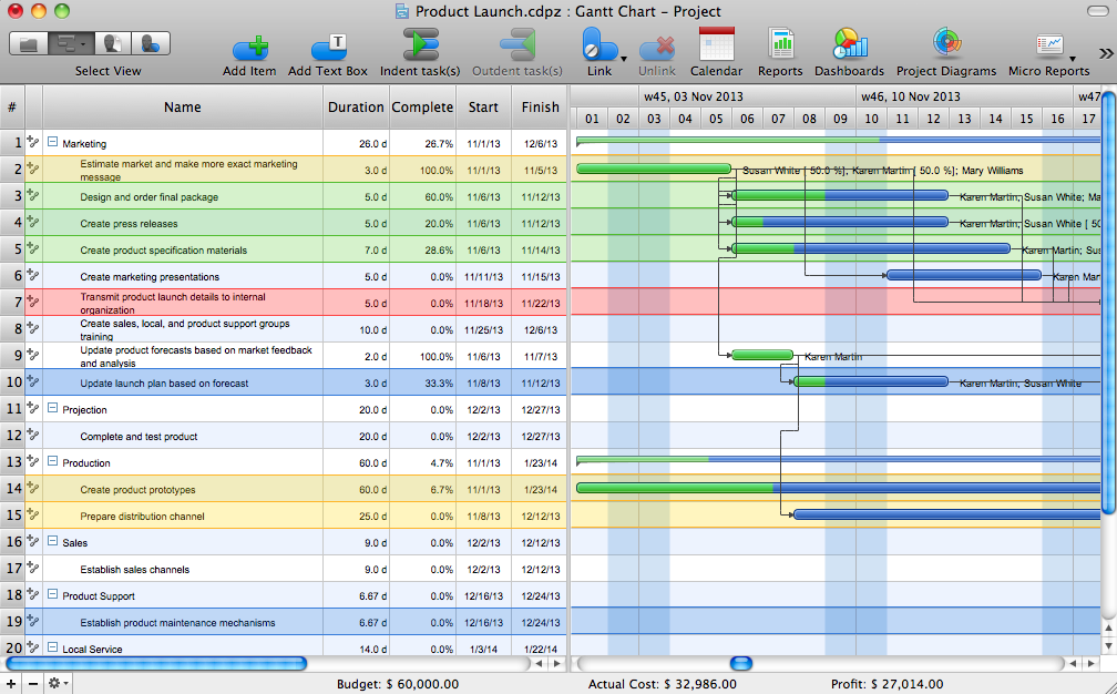
Gantt Chart Software
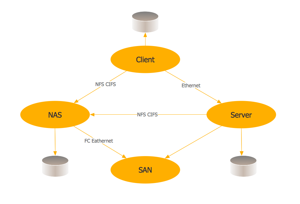
Storage area networks (SAN). Computer and Network Examples

Electrical Symbols, Electrical Diagram Symbols

Network Printer

Using Both Wired and Wireless Connections
Electrical Symbols — Semiconductor Diodes

Electrical and Telecom Plan Software

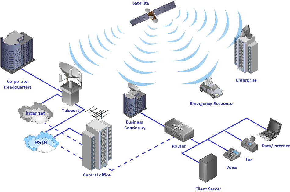
 Telecommunication Network Diagrams
Telecommunication Network Diagrams solution extends ConceptDraw DIAGRAM software with samples, templates, and great collection of vector stencils to help the specialists in a field of networks and telecommunications, as well as other users to create Computer systems networking and Telecommunication network diagrams for various fields, to organize the work of call centers, to design the GPRS networks and GPS navigational systems, mobile, satellite and hybrid communication networks, to construct the mobile TV networks and wireless broadband networks.
Telecommunications Network
- Wireless router network diagram | Wireless Network Mode | Cisco ...
- Wireless router network diagram | Computers and network isometric ...
- Images Of Telecommunication
- Lan Wan Man Network Images
- Network Gateway Router | Computer network - Vector stencils library ...
- Communication network diagram | Wireless router network diagram ...
- Communication network diagram | Computer network - Vector ...
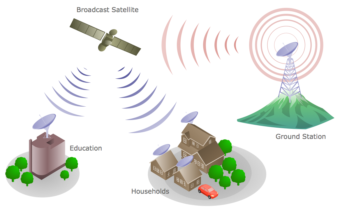
- Satellite telecom network diagram | Hybrid satellite and common ...
- Diagramming Software for Design UML Communication Diagrams ...
- Personal area (PAN) networks. Computer and Network Examples ...