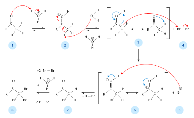
This chemical reaction mechanism drawing depicts steps of carbonyl compound halogenation reaction.
"Alpha-substitution reactions occur at the position next to the carbonyl group, the α-position, and involve the substitution of an α hydrogen atom by an electrophile, E, through either an enol or enolate ion intermediate. ...
Alpha Halogenation of Aldehydes and Ketones.
A particularly common α-substitution reaction in the laboratory is the halogenation of aldehydes and ketones at their α positions by reaction Cl2, Br2 or I2 in acidic solution. Bromine in acetic acid solvent is often used. ...
The halogenation is a typical α-substitution reaction that proceeds by acid catalyzed formation of an enol intermediate." [Carbonyl Alpha-Substitution Reactions. Wikipedia]
This example was redesigned from the Wikimedia Commons file: Halogenierung Mechanismus Version 3-Seite001.svg. [commons.wikimedia.org/ wiki/ File:Halogenierung_ Mechanismus_ Version_ 3-Seite001.svg]
This image is available under the Creative Commons Attribution-ShareAlike 3.0 Unported License. [creativecommons.org/ licenses/ by-sa/ 3.0/ ]
The chemical drawing example "Carbonyl compound halogenation mechanism" was created using the ConceptDraw PRO diagramming and vector drawing software extended with the Chemistry solution from the Science and Education area of ConceptDraw Solution Park.
Alpha halogenation of aldehydes and ketones
Metropolitan area networks (MAN). Computer and Network Examples
. Computer and Network Examples")

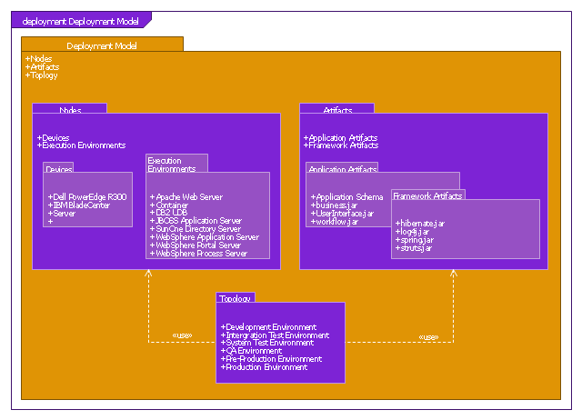
This SysML package diagram example was redesigned from the Wikimedia Commons file: Deployment Model Structure.PNG.
"Packages containing nodes and artifacts."
[commons.wikimedia.org/ wiki/ File:Deployment_ Model_ Structure.PNG]
This file is licensed under the Creative Commons Attribution-Share Alike 3.0 Unported license. [creativecommons.org/ licenses/ by-sa/ 3.0/ deed.en]
"Package diagrams can use packages containing use cases to illustrate the functionality of a software system.
Package diagrams can use packages that represent the different layers of a software system to illustrate the layered architecture of a software system. The dependencies between these packages can be adorned with labels / stereotypes to indicate the communication mechanism between the layers.
When To Use
- It is used in large scale systems to picture dependencies between major elements in the system
- Package diagrams represent a compile time grouping mechanism." [Package diagram. Wikipedia]
The example "Package diagram - Deployment model structure" was drawn using the ConceptDraw PRO diagramming and vector drawing software extended with the SysML solution from the Software Development area of ConceptDraw Solution Park.
SysML package diagram
IDEF0 standard with ConceptDraw DIAGRAM

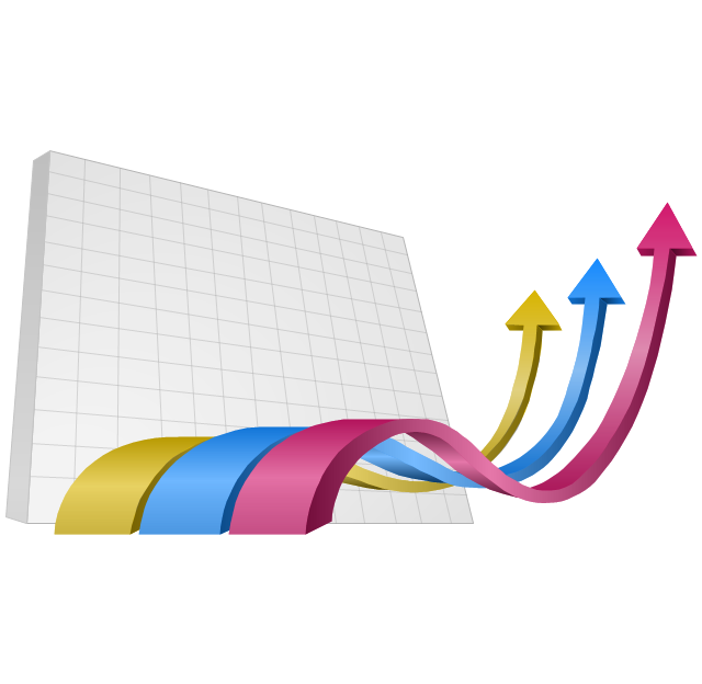
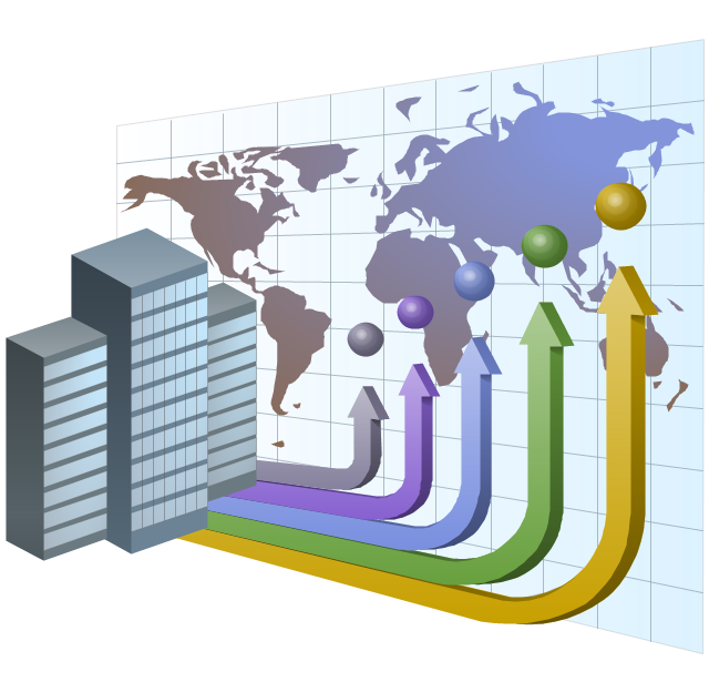
The vector clipart library "Presentation design elements" contains 45 presentation symbols and arrows which you can easy use in your slides and illustrations.
"A presentation is the process of presenting a topic to an audience. It is typically a demonstration, lecture, or speech meant to inform, persuade, or build good will. ... the use of visuals reduced meeting times... audiences believe presenters who use visuals are more professional and credible than presenters who merely speak. ... meetings and presentations reinforced with visuals help participants reach decisions and consensus more quickly." [Presentation. Wikipedia]
The clip art example "Presentation design elements - Vector clipart library" was created in the ConceptDraw PRO diagramming and vector drawing software using the Presentation Clipart solution from the Illustration area of ConceptDraw Solution Park.
Advance Direction Sign

Circuit

Growth
Master Link

Comparison

Plus

Minus

Multiplication

Division

Loupe

Plus sign

Minus sign

Pros and Cons
Balance Lever

Balance

Scientific Research

Business People

Hand

Financial Growth

Wallet

Increase

Decrease

Clock

Mechanism

Interaction

Small Company

Big Company

Company Expansion

Foreign Market Entry
Time

Close Cooperation

Company

Company Merger

Company Extension

Foreign Market Penetration

Business Relations

Profits

Frame 1

Frame 2

Background 1

Background 2

Background 3

Background 4

Background 5

Title block

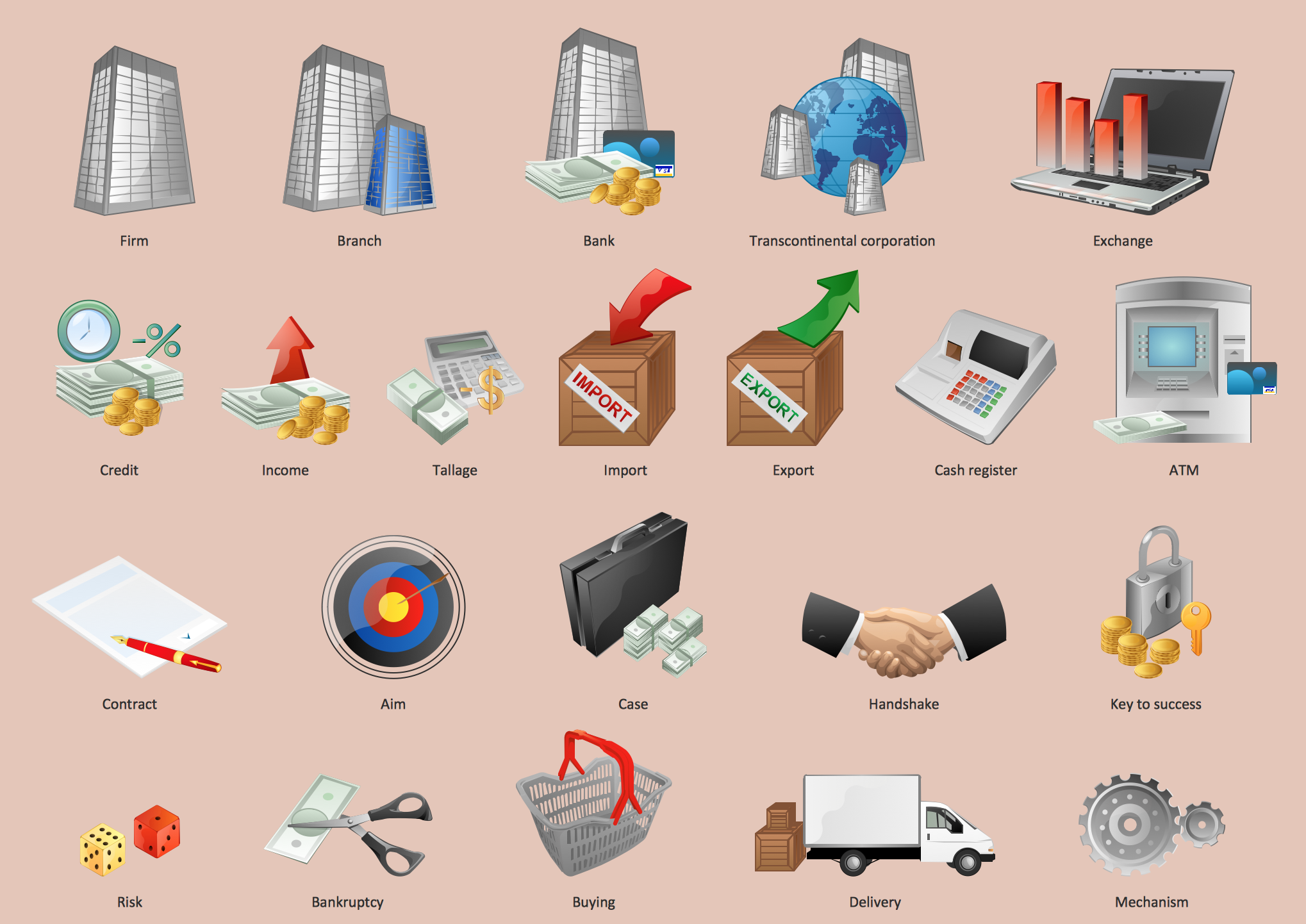
The vector stencils library "Business" contains 24 business icons.
Use it to design your business and finance illustrations and infographics with ConceptDraw PRO diagramming and vector drawing software.
The vector stencils library "Business" is included in the Business and Finance solution from the Illustration area of ConceptDraw Solution Park.
Use it to design your business and finance illustrations and infographics with ConceptDraw PRO diagramming and vector drawing software.
The vector stencils library "Business" is included in the Business and Finance solution from the Illustration area of ConceptDraw Solution Park.
Company

Office branch

Bank

Income

Exchange

Business statistics

Mechanism

Commerce

Handshake

Business contract

Reporting

Risk

Targeting

Key to success

Transcontinental corporation

Credit debt

Taxes

Bankruptcy

Money case

ATM

Cash register

Buying

Exhibition

Delivery

Chemistry Equation Symbols

Business - Design Elements
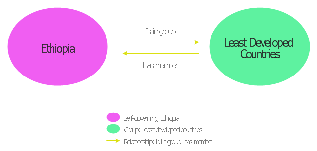
This concept map example shows concepts and relationship in the geopolitical ontology.
"A geopolitical ontology is a mechanism to describe, manage and exchange data related to geopolitical entities such as countries, territories, regions and other similar areas. ...
An Ontology is a kind of dictionary that describes information in a certain domain using concepts and relationships. It is often implemented using OWL (Web Ontology Language), an XML-based standard language that can be interpreted by computers." [Geopolitical ontology. Wikipedia]
This concept map example was redesigned from the Wikimedia Commons file: Concepts November 19 2008 v 2.png. [commons.wikimedia.org/ wiki/ File:Concepts_ November_ 19_ 2008_ v_ 2.png]
This file is licensed under the Creative Commons Attribution-Share Alike 3.0 Unported license. [creativecommons.org/ licenses/ by-sa/ 3.0/ deed.en]
The example "Concepts and relationship in the geopolitical ontology" was created using the ConceptDraw PRO diagramming and vector drawing software extended with the Concept Maps solution from the area "What is a Diagram" of ConceptDraw Solution Park.
Concept map
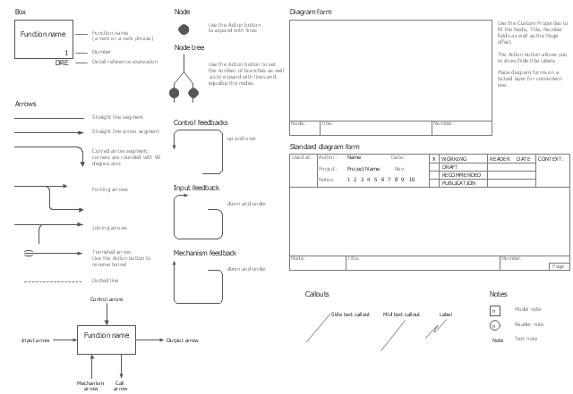
The vector stencils library "IDEF0" contains 26 IDEF0 diagram symbols.
Use it for business process modeling with IDEF0 diagrams.
"The IDEF0 model ... is based on a simple syntax. Each activity is described by a verb-based label placed in a box. Inputs are shown as arrows entering the left side of the activity box while output are shown as exiting arrows on the right side of the box. Controls are displayed as arrows entering the top of the box and mechanisms are displayed as arrows entering from the bottom of the box. Inputs, Controls, Outputs, and Mechanisms are all referred to as concepts.
- Arrow: A directed line, composed of one or more arrow segments, that models an open channel or conduit conveying data or objects from source (no arrowhead) to use (with arrowhead). There are 4 arrow classes: Input Arrow, Output Arrow, Control Arrow, and Mechanism Arrow (includes Call Arrow). See Arrow Segment, Boundary Arrow, Internal Arrow.
- Box: A rectangle, containing a name and number, used to represent a function.
- Context: The immediate environment in which a function (or set of functions on a diagram) operates.
- Decomposition: The partitioning of a modeled function into its component functions.
- Fork: The junction at which an IDEF0 arrow segment (going from source to use) divides into two or more arrow segments. May denote unbundling of meaning.
- Function: An activity, process, or transformation (modeled by an IDEF0 box) identified by a verb or verb phrase that describes what must be accomplished.
- Join: The junction at which an IDEF0 arrow segment (going from source to use) merges with one or more other arrow segments to form a single arrow segment. May denote bundling of arrow segment meanings.
- Node: A box from which child boxes originate; a parent box. See Node Index, Node Tree, Node Number, Node Reference, Diagram Node Number." [IDEF0. Wikipedia]
The shapes example "Design elements - IDEF0" was created using the ConceptDraw PRO diagramming and vector drawing software extended with the solution "IDEF Business Process Diagrams" from the area "Business Processes" of ConceptDraw Solution Park.
IDEF0 diagram symbols
- Mechanism Clipart Png Image
- Time For Expansion Clip Art Png
- Business - Vector stencils library | Shake Hand Vector Png
- Business - Vector stencils library | People | Handshake In Circle Png ...
- Business - Vector stencils library | Shake Hand Png
- Icon Png Debt
- Exchange Money Png Vector
- Chemistry Equation Symbols | Business - Vector stencils library ...
- Vector Backgrounds Png