 Mechanical Engineering
This solution extends ConceptDraw DIAGRAM.9 mechanical drawing software (or later) with samples of mechanical drawing symbols, templates and libraries of design elements, for help when drafting mechanical engineering drawings, or parts, assembly, pneumatic,
Mechanical Drawing Symbols

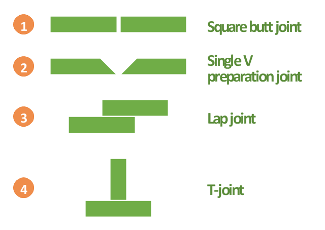
"A welding joint is a point or edge where two or more pieces of metal or plastic are joined together. They are formed by welding two or more workpieces (metal or plastic) according to a particular geometry. Five types of joints referred to by the American Welding Society: butt, corner, edge, lap, and tee. These configurations may have various configurations at the joint where actual welding can occur." [Welding joint. Wikipedia]
This engineering drawing example was redesigned using the ConceptDraw PRO diagramming and vector drawing software from the Wikimedia Commons file: Common joint types.png.
[commons.wikimedia.org/ wiki/ File:Common_ joint_ types.png]
This file is licensed under the Creative Commons Attribution-Share Alike 3.0 Unported license.
[creativecommons.org/ licenses/ by-sa/ 3.0/ deed.en]
The engineering drawing example "Common joint types" is included in the Mechanical Engineering solution from the Engineering area of ConceptDraw Solution Park.
Welding joint types
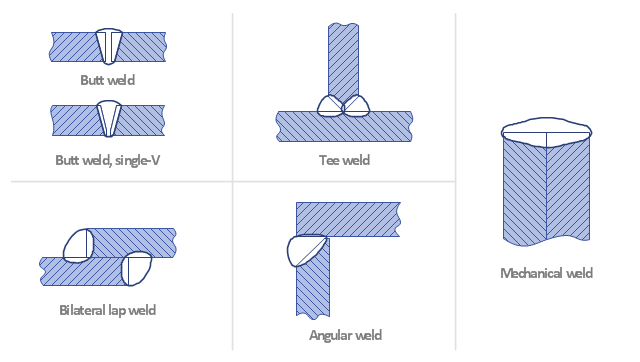
"A welding joint is a point or edge where two or more pieces of metal or plastic are joined together. They are formed by welding two or more workpieces (metal or plastic) according to a particular geometry. Five types of joints referred to by the American Welding Society: butt, corner, edge, lap, and tee. These configurations may have various configurations at the joint where actual welding can occur." [Welding joint. Wikipedia]
The engineering drawing example "Welded joints types" was created using the ConceptDraw PRO diagramming and vector drawing software extended with the Mechanical Engineering solution from the Engineering area of ConceptDraw Solution Park.
The engineering drawing example "Welded joints types" was created using the ConceptDraw PRO diagramming and vector drawing software extended with the Mechanical Engineering solution from the Engineering area of ConceptDraw Solution Park.
Welding joints
Mechanical Engineering

Process Flow Diagram Symbols

Systems Engineering

Electrical Symbols — Rotating Equipment

Interior Design. Machines and Equipment — Design Elements

Technical Drawing Software

- Mechanical Engineering | How Many Types Of Mechanical Drawing
- Welded joints types | Mechanical Engineering | Butt weld geometry ...
- Design elements - Pumps | Mechanical Engineering | Design ...
- Welding symbols | Design elements - Pipes (part 1) | Mechanical ...
- Mechanical Engineering | Types Of Datum In Engineering
- Mechanical Engineering | Technical drawing - Machine parts ...
- Mechanical Engineering | Welded joints types | Technical drawing ...
- Types Of Hydraulic Valve Symbils
- Mechanical Engineering | Design elements - Welding | Design ...
- Mechanical Engineering | Types Of Datum In Geometric Symbols