Mechanical Drawing Symbols

Process Flowchart


Basic Flowchart Symbols and Meaning


Mechanical Engineering

The vector stencils library "Bearings" contains 59 symbols of ball bearings, roller bearings, shafts, springs, gears, hooks, spindles, and keys.
Use it to design engineering drawings of machine tools and mechanical devices.
"A bearing is a machine element that constrains relative motion and reduce friction between moving parts to only the desired motion. The design of the bearing may, for example, provide for free linear movement of the moving part or for free rotation around a fixed axis; or, it may prevent a motion by controlling the vectors of normal forces that bear on the moving parts. Many bearings also facilitate the desired motion as much as possible, such as by minimizing friction. Bearings are classified broadly according to the type of operation, the motions allowed, or to the directions of the loads (forces) applied to the parts." [Bearing (mechanical). Wikipedia]
The shapes example "Design elements - Bearings" was created using the ConceptDraw PRO diagramming and vector drawing software extended with the Mechanical Engineering solution from the Engineering area of ConceptDraw Solution Park.
Bearing symbols

Process Engineering

 Chemical and Process Engineering
This chemical engineering solution extends ConceptDraw PRO v.9.5 (or later) with process flow diagram symbols, samples, process diagrams templates and libraries of design elements for creating process and instrumentation diagrams, block flow diagrams (BFD
The vector stencils library "Welding" contains 38 welding joint symbols to identify fillets, contours, resistance seams, grooves, surfacing, and backing.
Use it to indicate welding operations on working drawings.
"Welding is a fabrication or sculptural process that joins materials, usually metals or thermoplastics, by causing coalescence. This is often done by melting the workpieces and adding a filler material to form a pool of molten material (the weld pool) that cools to become a strong joint, with pressure sometimes used in conjunction with heat, or by itself, to produce the weld. This is in contrast with soldering and brazing, which involve melting a lower-melting-point material between the workpieces to form a bond between them, without melting the workpieces.
Many different energy sources can be used for welding, including a gas flame, an electric arc, a laser, an electron beam, friction, and ultrasound.
Welds can be geometrically prepared in many different ways. The five basic types of weld joints are the butt joint, lap joint, corner joint, edge joint, and T-joint (a variant of this last is the cruciform joint). Other variations exist as well - for example, double-V preparation joints are characterized by the two pieces of material each tapering to a single center point at one-half their height. Single-U and double-U preparation joints are also fairly common - instead of having straight edges like the single-V and double-V preparation joints, they are curved, forming the shape of a U. Lap joints are also commonly more than two pieces thick - depending on the process used and the thickness of the material, many pieces can be welded together in a lap joint geometry." [Welding. Wikipedia]
The shapes example "Design elements - Welding" was created using the ConceptDraw PRO diagramming and vector drawing software extended with the Mechanical Engineering solution from the Engineering area of ConceptDraw Solution Park.
Welding joint symbols

The vector stencils library "Pumps" contains 82 symbols of pumps, compressors, fans, turbines, and power generators.
Use these icons to design pumping systems, air and fluid compression systems, and industrial process diagrams.
"A pump is a device that moves fluids (liquids or gases), or sometimes slurries, by mechanical action. Pumps can be classified into three major groups according to the method they use to move the fluid: direct lift, displacement, and gravity pumps.
Pumps operate by some mechanism (typically reciprocating or rotary), and consume energy to perform mechanical work by moving the fluid. Pumps operate via many energy sources, including manual operation, electricity, engines, or wind power, come in many sizes, from microscopic for use in medical applications to large industrial pumps.
Mechanical pumps serve in a wide range of applications such as pumping water from wells, aquarium filtering, pond filtering and aeration, in the car industry for water-cooling and fuel injection, in the energy industry for pumping oil and natural gas or for operating cooling towers. In the medical industry, pumps are used for biochemical processes in developing and manufacturing medicine, and as artificial replacements for body parts, in particular the artificial heart and penile prosthesis.
In biology, many different types of chemical and bio-mechanical pumps have evolved, and biomimicry is sometimes used in developing new types of mechanical pumps." [Pump. Wikipedia]
The example "Design elements - Pumps" was created using the ConceptDraw PRO diagramming and vector drawing software extended with the Chemical and Process Engineering solution from the Engineering area of ConceptDraw Solution Park.
Pump symbols

Electrical Engineering

 Event-driven Process Chain Diagrams
Event-driven Process Chain (EPC) Diagram is a type of flowchart widely used for modeling in business engineering and reengineering, business process improvement, and analysis. EPC method was developed within the Architecture of Integrated Information Systems (ARIS) framework.
 Audit Flowcharts
Audit flowcharts solution extends ConceptDraw PRO software with templates, samples and library of vector stencils for drawing the audit and fiscal flow charts.
The vector stencils library "Welding" contains 38 welding joint symbols to identify fillets, contours, resistance seams, grooves, surfacing, and backing.
Use it to indicate welding operations on working drawings in the ConceptDraw PRO diagramming and vector drawing software extended with the Mechanical Engineering solution from the Engineering area of ConceptDraw Solution Park.
www.conceptdraw.com/ solution-park/ engineering-mechanical
Use it to indicate welding operations on working drawings in the ConceptDraw PRO diagramming and vector drawing software extended with the Mechanical Engineering solution from the Engineering area of ConceptDraw Solution Park.
www.conceptdraw.com/ solution-park/ engineering-mechanical
Additional arrow
Text block

Fillet

Slot / plug

Stud

Resistance seam

Backing

Surfacing

Flange corner

Flange edge

Square groove

V-groove

Bevel groove

U-groove

J-groove

Flare V groove

Flare bevel groove

Scarf

Melt through weld

Field weld

Backing / spacer

Insert

Arrow with bend
Arrow with bend, tail
Arrow with bend, circle
Arrow with bend, circle, tail
Arrow
Arrow, tail

Arrow, circle

Arrow, circle, tail

Spot

Projection weld

Contour, concave

Contour, convex

Contour, flush

Contour angled, concave

Contour angled, convex

Contour angled, flush

Square butt weld

Closed square butt weld

Single-bevel butt weld

Double-bevel butt weld

Single-V butt weld

Double-V butt weld

Single-J butt weld

Double-J butt weld

Single-U butt weld

Double-U butt weld

Flange butt weld

Tee butt weld

Flare butt weld

Square butt joint

Single V preparation joint

Lap joint

T-joint

Butt weld

Butt weld, single-V

Bilateral lap weld

Tee weld

Angular weld

Mechanical weld

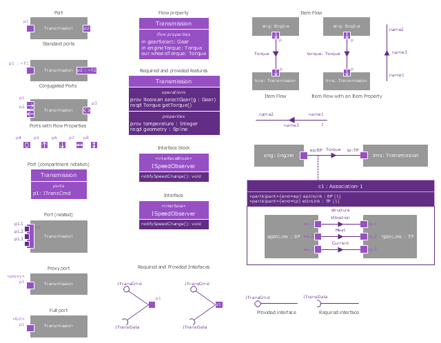
The vector stencils library "Ports and Flows" contains 26 SysML symbols.
Use it to design your SysML diagrams using ConceptDraw PRO diagramming and vector drawing software.
"The main motivation for specifying ports and flows is to enable design of modular, reusable blocks with clearly defined
ways of connecting and interacting with their context of use. This clause extends UML ports to support nested ports, and
extends blocks to support flow properties, and required and provided features, including blocks that type ports. Ports can be typed by blocks that support operations, receptions, and properties as in UML. SysML defines a specialized form of Block (InterfaceBlock) that can be used to support nested ports. SysML identifies two kinds of ports, one that exposes
features of the owning block or its internal parts (proxy ports), and another that supports its own features (full ports). Default compatibility rules are defined for connecting blocks used in composite structure, including parts and ports, with association blocks available to define more specific ways of doing this. These additional capabilities in SysML enable modelers to specify a wide variety of interconnectable components, which can be implemented through many engineering and social techniques, such as software, electrical or mechanical components, and human organizations. This clause also extends UML information flows for specifying item flows across connectors and associations." [www.omg.org/ spec/ SysML/ 1.3/ PDF]
The SysML shapes example "Design elements - Ports and Flows" is included in the SysML solution from the Software Development area of ConceptDraw Solution Park.
SysML ports and flows symbols
- Mechanical Drawing Symbols | Mechanical Engineering | Elements ...
- Mechanical Drawing Symbols | Process Flow Diagram Symbols ...
- Mechanical Drawing Symbols | Process Flow Diagram Symbols ...
- Mechanical Engineering | Technical drawing - Machine parts ...
- Chemical and Process Engineering | Mechanical Drawing Symbols ...
- Mechanical Engineering | Process Flowchart | Mechanical ...
- Mechanical Engineering | Engineering | Chemical and Process ...
- Mechanical Engineering | Engineering | Technical Drawing Software ...
- Mechanical Drawing Symbols | Welding symbols | Mechanical ...
- Machine Drawing Symbols For Different Operation
- Process Flowchart | Electrical Engineering | Technical Drawing ...
- Mechanical Engineering Drawing Symbol In Pdf Of Industries
- Mechanical Drawing Symbols | Technical Drawing Software ...
- Mechanical Drawing Symbols | Elements location of a welding ...
- Electrical Drawing Software | Process Flowchart | Technical Drawing ...
- Chemical Process Symbols
- Mechanical Drawing Symbols | Entity Relationship Diagram ...
- Drawings Of A Chemical Engineer
- Mechanical Drawing Symbols | Technical Drawing Software ...
- Elements location of a welding symbol | Building Drawing