Cisco People. Cisco icons, shapes, stencils and symbols
The vector stencils library "UML use case diagrams" contains 25 symbols for the ConceptDraw PRO diagramming and vector drawing software.
"Use case diagrams are usually referred to as behavior diagrams used to describe a set of actions (use cases) that some system or systems (subject) should or can perform in collaboration with one or more external users of the system (actors). Each use case should provide some observable and valuable result to the actors or other stakeholders of the system. ...
Use case diagrams are in fact twofold - they are both behavior diagrams, because they describe behavior of the system, and they are also structure diagrams - as a special case of class diagrams where classifiers are restricted to be either actors or use cases related to each other with associations. ...
Use case is usually shown as an ellipse containing the name of the use case. ...
Name of the use case could also be placed below the ellipse. ...
If a subject (or system boundary) is displayed, the use case ellipse is visually located inside the system boundary rectangle. Note, that this does not necessarily mean that the subject classifier owns the contained use cases, but merely that the use case applies to that classifier. ...
A list of use case properties - operations and attributes - could be shown in a compartment within the use case oval below the use case name. ...
Use case with extension points may be listed in a compartment of the use case with the heading extension points. ...
A use case can also be shown using the standard rectangle notation for classifiers with an ellipse icon in the upper right-hand corner of the rectangle and with optional separate list compartments for its features. ...
Subject (sometimes called a system boundary) is presented by a rectangle with subject's name, associated keywords and stereotypes in the upper left corner. Use cases applicable to the subject are located inside the rectangle and actors - outside of the system boundary. ...
Standard UML notation for actor is "stick man" icon with the name of the actor above or below of the icon. Actor names should follow the capitalization and punctuation guidelines for classes. The names of abstract actors should be shown in italics. ...
Custom icons that convey the kind of actor may also be used to denote an actor, such as using a separate icon(s) for non-human actors. ...
An actor may also be shown as a class rectangle with the standard keyword «actor», having usual notation for class compartments ...
An actor can only have binary associations to use cases, components, and classes. ...
An association between an actor and a use case indicates that the actor and the use case somehow interact or communicate with each other.
Only binary associations are allowed between actors and use cases.
An actor could be associated to one or several use cases. ...
A use case may have one or several associated actors." [uml-diagrams.org/ use-case-diagrams.html]
The example "Design elements - UML use case diagrams" is included in the Rapid UML solution from the Software Development area of ConceptDraw Solution Park.
UML use case diagram symbols

Local area network (LAN). Computer and Network Examples
 diagram")

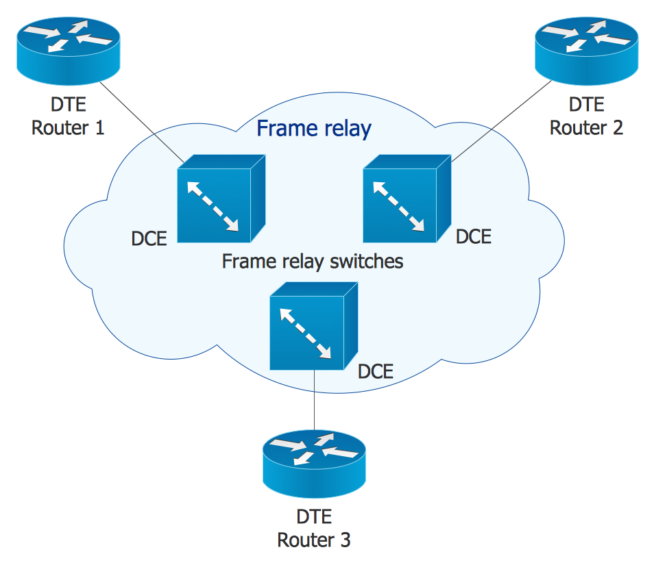
Cisco Network Topology. Cisco icons, shapes, stencils and symbols

Design Element: Computer and Network for Network Diagrams
.png)
Cisco Network Design. Cisco icons, shapes, stencils, symbols and design elements

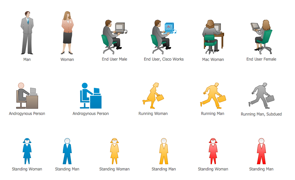
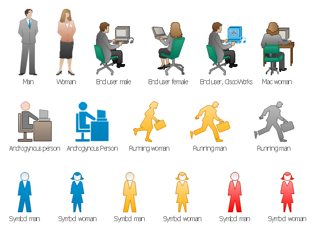
The vector stencils library "Cisco people" contains 17 pictogram symbols and clipart icons of people: Man, Woman, End user male and female, End user Cisco works, Mac woman, Androgynous person, Running woman and man, Symbols men and women.
Create the computer network diagrams using the ConceptDraw PRO diagramming and vector drawing software with the design elements library "Cisco people".
The example "Design elements - Cisco people" is included in the Cisco Network Diagrams solution from the Computer and Networks area of ConceptDraw Solution Park.
Cisco people symbols
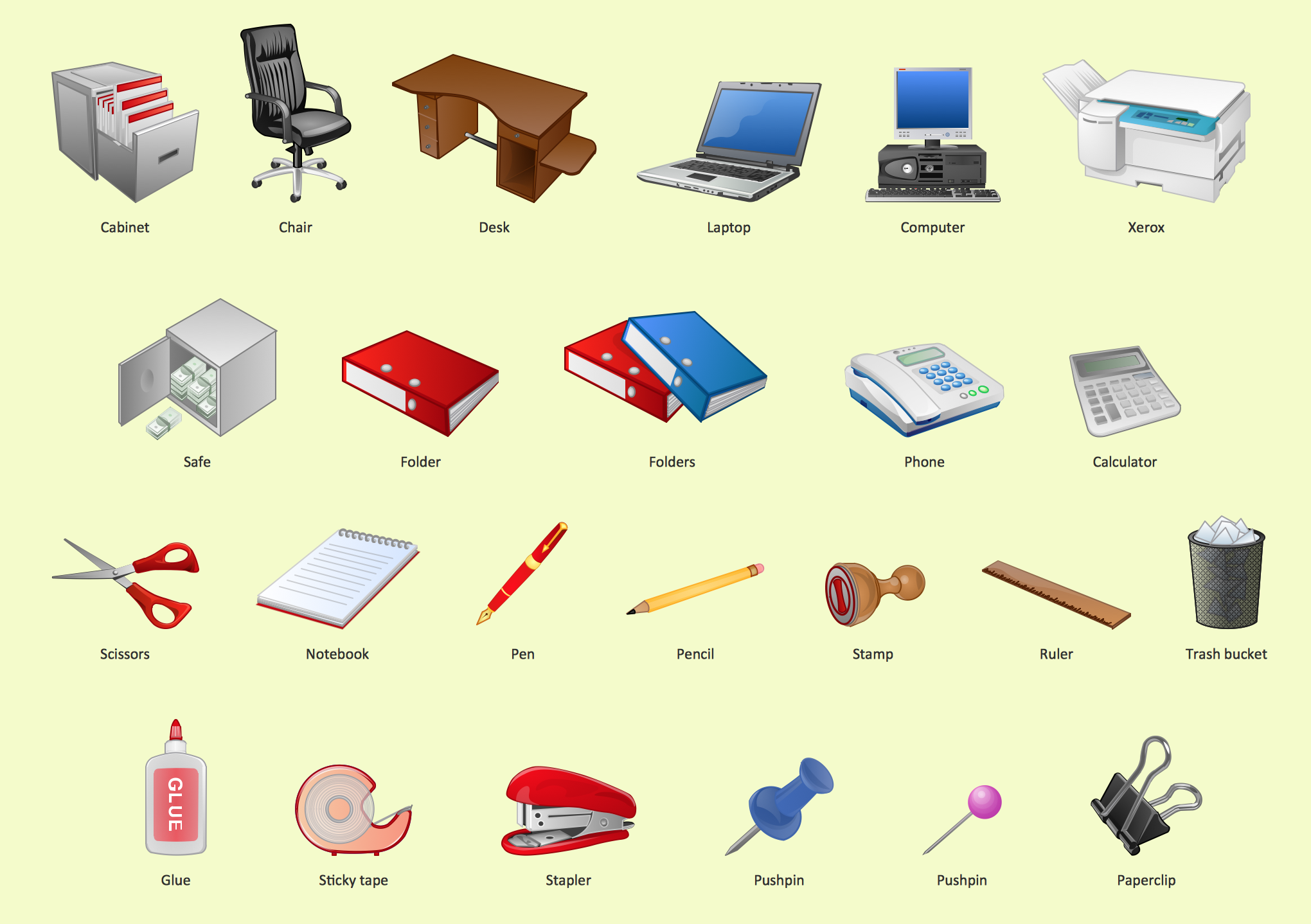
Office - Design Elements
Cisco Network Icons
ERD Symbols and Meanings


Marketing - Design Elements
The vector stencils library "Cloud clipart" contains 195 icons.
Use it to design your cloud computing infographics and diagrams with ConceptDraw PRO software.
"Cloud computing, also known as 'on-demand computing', is a kind of Internet-based computing, where shared resources, data and information are provided to computers and other devices on-demand. It is a model for enabling ubiquitous, on-demand access to a shared pool of configurable computing resources. Cloud computing and storage solutions provide users and enterprises with various capabilities to store and process their data in third-party data centers. It relies on sharing of resources to achieve coherence and economies of scale..." [Cloud computing. Wikipedia]
The icon set example "Design elements - Cloud clipart" is included in the Cloud Computing Diagrams solution from the Computer and Networks area from ConceptDraw Solution Park.
Cloud computing icons
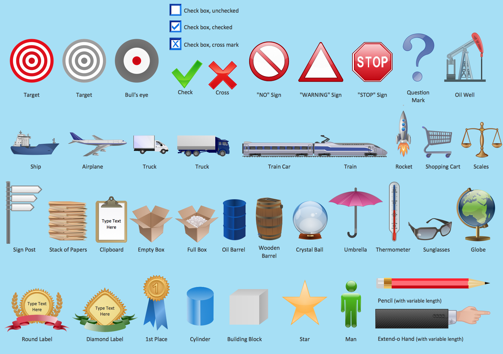
The vector stencils library "Sales symbols" contains 55 sales process pictograms.
Use it to design your sales flowcharts, workflow diagrams and process charts by the ConceptDraw PRO diagramming and vector drawing software.
"A sales process is an approach to selling a product or service.
... a "sales process" is presented as consisting of eight steps. These are:
(1) Prospecting / initial contact,
(2) Preapproach - planning the sale,
(3) Identifying and cross questioning,
(4) Need assessment,
(5) Presentation,
(6) Meeting objections,
(7) Gaining commitment,
(8) Follow-up." [Sales process. Wikipedia]
The icons example "Design elements - Sales symbols" is included in the Sales Flowcharts solution from the Marketing area of ConceptDraw Solution Park.
Sales icon set
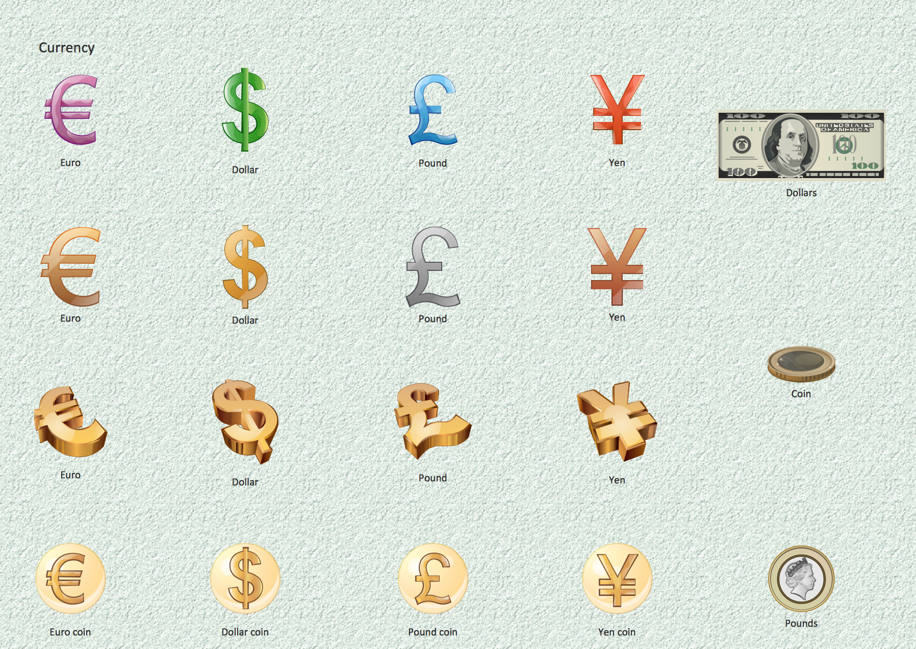
Currency - Design Elements
- Sales symbols - Vector stencils library | Caler Man Icon
- Design elements - UML use case diagrams | HR professions ...
- Design elements - Sales symbols | Sales symbols - Vector stencils ...
- Electronic Service Man Icon
- Cisco People. Cisco icons , shapes, stencils and symbols | Design ...
- Phone Man Icon
- Network Icon | Network Architecture | Metropolitan area networks ...
- People pictograms - Vector stencils library | App icons - Vector ...
- Man Sitting In A Chair Png Icon
- Sales symbols - Vector stencils library | Design elements - Sales ...
- Cisco People. Cisco icons , shapes, stencils and symbols | Cisco ...
- People pictograms - Vector stencils library | Design elements ...
- Cisco People. Cisco icons , shapes, stencils and symbols | Design ...
- Design elements - Scrum people | Design elements - Cisco people ...
- Telecom - Vector stencils library | Design elements - Telecom ...
- Design elements - UML use case diagrams | Diagramming software ...
- Money - Design Elements | Cloud clipart - Vector stencils library ...
- Design elements - Marketing pictograms | Design elements ...
- Running Man Pictogram
- Cisco people - Vector stencils library | Cisco People. Cisco icons ...