A conceptual diagram of a global vehicular network describes the principles of communication between vehicles, earth-based nodes, and space-based nodes in a wireless network. It illustrates the concept of architecture within global vehicular networks.
"Intelligent transportation systems (ITS) are advanced applications which, without embodying intelligence as such, aim to provide innovative services relating to different modes of transport and traffic management and enable various users to be better informed and make safer, more coordinated, and 'smarter' use of transport networks.
...
Intelligent transport systems vary in technologies applied, from basic management systems such as car navigation; traffic signal control systems; container management systems; variable message signs; automatic number plate recognition or speed cameras to monitor applications, such as security CCTV systems; and to more advanced applications that integrate live data and feedback from a number of other sources, such as parking guidance and information systems; weather information; bridge deicing systems; and the like." [Intelligent transportation system. Wikipedia]
The global vehicular network diagram template is included in the Vehicular Networking solution from the Computer and Networks area of ConceptDraw Solution Park.
Global vehicular network diagram template
This network diagram sample depicts the cooperative delay-tolerant vehicular communication system.
"Vehicular Communication Systems are an emerging type of networks in which vehicles and roadside units are the communicating nodes; providing each other with information, such as safety warnings and traffic information. As a cooperative approach, vehicular communication systems can be more effective in avoiding accidents and traffic congestions than if each vehicle tries to solve these problems individually.
Generally vehicular networks are considered to contain two types of nodes; vehicles and roadside stations. Both are Dedicated Short Range Communications (DSRC) devices. DSRC works in 5.9 GHz band with bandwidth of 75 MHz and approximate range of 1000m. The network should support both private data communications and public (mainly safety) communications but higher priority is given to public communications. Vehicular communications is usually developed as a part of Intelligent Transport Systems (ITS). ITS seeks to achieve safety and productivity through intelligent transportation which integrates communication between mobile and fixed nodes. To this end ITS heavily relies on wired and wireless communications." [Vehicular communication systems. Wikipedia]
The diagram example "Cooperative vehicular delay-tolerant network" was created using the ConceptDraw PRO diagramming and vector drawing software extended with the Vehicular Networking solution from the Computer and Networks area of ConceptDraw Solution Park.
Vehicular communication system diagram
 Vehicular Networking
The Vehicular Networking solution extends the ConceptDraw DIAGRAM software functionality with specialized tools, wide variety of pre-made vector objects, collection of samples and templates in order to help network engineers design vehicular network diagrams for effective network engineering activity, visualize vehicular networks, develop smart transportation systems, design various types of vehicle network management diagrams, regional network diagrams, vehicular communication system diagrams, vehicular ad-hoc networks, vehicular delay-tolerant networks, and other network engineering schemes.
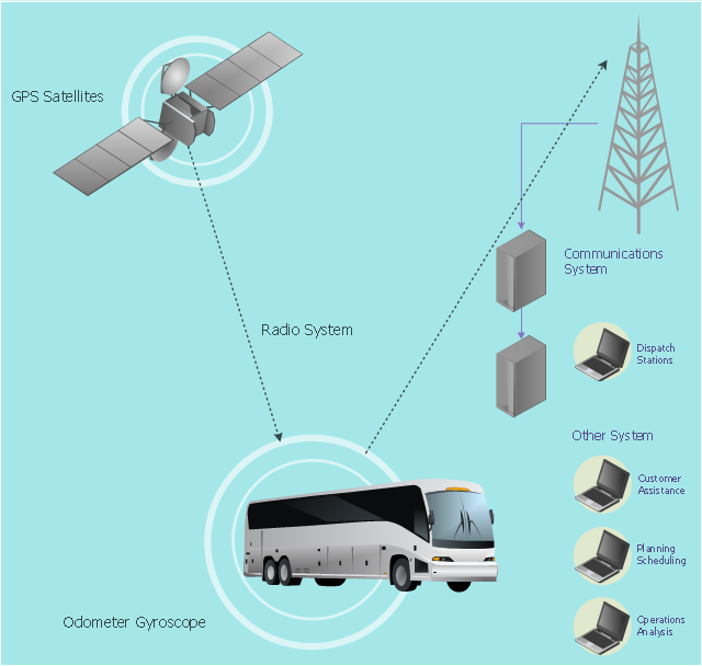
This vehicular network diagram example was drawn on the base of picture illustrating the article "Automatic Vehicle Location: Rural Transit" from the website of the Research and Innovative Technology Administration (RITA), U.S. Department of Transportation (US DOT).
"Automatic Vehicle Location (AVL) systems calculate the real-time location of any vehicle equipped with a Global Positioning Satellite (GPS) receiver. Data are then transmitted to the transit center with use of radio or cellular communications and can be used immediately for daily operations as well as archived for further analysis.
As a stand-alone technology, an AVL system can be used to monitor on-time performance. When combined with other technologies, AVL can deliver many benefits in the areas of fleet management, service planning, safety and security, traveler information, fare payment, vehicle component monitoring, and data collection. Since the greatest benefits from AVL are achieved by combining it with other Intelligent Transportation System (ITS) technologies, AVL is most appropriate for large rural agencies with more than 30 vehicles that plan to implement a comprehensive ITS."
[pcb.its.dot.gov/ factsheets/ avl/ avlRural_ overview.asp]
The vehicular network diagram example "Automatic vehicle location" was created using the ConceptDraw PRO diagramming and vector drawing software extended with the Vehicular Networking solution from the Computer and Networks area of ConceptDraw Solution Park.
Vehicular network diagram
Used Solutions
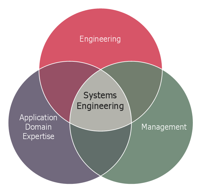
This Venn diagram sample shows the system engineering at the intersection of enginnering, management, and application domain expertise. It was designed on the base of the Venn diagram on the webpage "Intelligent Transportation Systems (ITS) ePrimer, Module 2: Systems Engineering" from the website of the Office of the Assistant Secretary for Research and Technology (OST-R), the U.S. Department of Transportation (US DOT).
"The term interdisciplinary is a fundamental concept in systems engineering. To successfully develop a system requires the application of basic engineering discipline, management discipline, and expertise in the application domain of the system. In the case of ITS, that application domain is transportation engineering. The intersection of these disciplines is the realm of systems engineering."
[pcb.its.dot.gov/ eprimer/ module2.aspx]
The Venn diagram example "Systems engineering improvement" was created using the ConceptDraw PRO diagramming and vector drawing software extended with the Venn Diagrams solution from the area "What is a Diagram" of ConceptDraw Solution Park.
Venn diagram
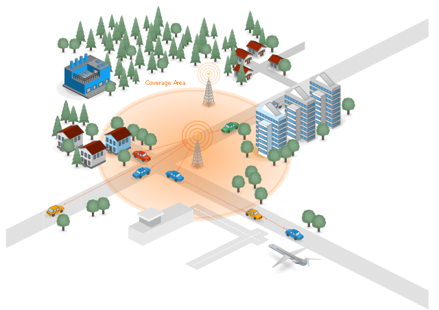
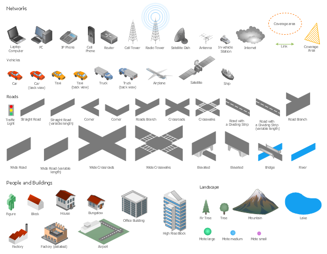
The vector stencils library "Local vehicular networking" contains 88 symbols for drawing the vehicular computer telecommunication network diagrams using the ConceptDraw PRO diagramming and vector drawing software.
"A vehicular ad hoc network (VANET) uses cars as mobile nodes in a MANET to create a mobile network.[1] A VANET turns every participating car into a wireless router or node, allowing cars approximately 100 to 300 metres of each other to connect and, in turn, create a network with a wide range. As cars fall out of the signal range and drop out of the network, other cars can join in, connecting vehicles to one another so that a mobile Internet is created. It is estimated that the first systems that will integrate this technology are police and fire vehicles to communicate with each other for safety purposes. ...
Vehicular ad hocal networks are expected to implement wireless technologies such as dedicated short-range communications (DSRC) which is a type of Wi-Fi. Other candidate wireless technologies are cellular, satellite, and WiMAX. Vehicular ad hoc networks can be viewed as component of the intelligent transportation systems (ITS).
As promoted in ITS, vehicles communicate with each other via inter-vehicle communication (IVC) as well as with roadside base stations via roadside-to-vehicle communication (RVC)." [Vehicular ad hoc network. Wikipedia]
The example "Design elements - Local vehicular networking" is included in the Vehicular Networking solution from the Computer and Networks area of ConceptDraw Solution Park.
Vehicular network diagram symbols
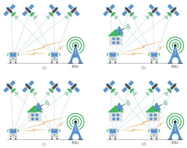
This diagram sample shows the different situations that cooperative positioning may be helpful for vehicular networks. It was designed on the base of Wikimedia Commons file: CPsituations.jpg.
[commons.wikimedia.org/ wiki/ File:CPsituations.jpg]
"Vehicular Ad Hoc Networks (VANETs) are created by applying the principles of mobile ad hoc networks (MANETs) - the spontaneous creation of a wireless network for data exchange - to the domain of vehicles. They are a key component of intelligent transportation systems (ITS).
While, in the early 2000s, VANETs were seen as a mere one-to-one application of MANET principles, they have since then developed into a field of research in their own right. By 2015, the term VANET became mostly synonymous with the more generic term inter-vehicle communication (IVC), although the focus remains on the aspect of spontaneous networking, much less on the use of infrastructure like Road Side Units (RSUs) or cellular networks." [Vehicular ad hoc network. Wikipedia]
The vehicular network diagram example "CP situations" was created using the ConceptDraw PRO diagramming and vector drawing software extended with the Computers and Communications solution from the Illustration area of ConceptDraw Solution Park.
Telecommunication diagram
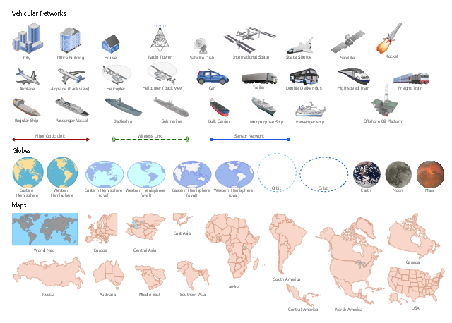
"Intelligent vehicular ad hoc networks (InVANETs) use WiFi IEEE 802.11p (WAVE standard) and WiMAX IEEE 802.16 for easy and effective communication between vehicles with dynamic mobility. Effective measures such as media communication between vehicles can be enabled as well methods to track automotive vehicles. InVANET is not foreseen to replace current mobile (cellular phone) communication standards . ...
Communication capabilities in vehicles are the basis of an envisioned InVANET or intelligent transportation systems (ITS). Vehicles are enabled to communicate among themselves (vehicle-to-vehicle, V2V) and via roadside access points (vehicle-to-roadside, V2R) also called as Road Side Units (RSUs). Vehicular communication is expected to contribute to safer and more efficient roads by providing timely information to drivers, and also to make travel more convenient. The integration of V2V and V2R communication is beneficial because V2R provides better service sparse networks and long distance communication, whereas V2V enables direct communication for small to medium distances/ areas and at locations where roadside access points are not available." [Intelligent vehicular ad-hoc network. Wikipedia]
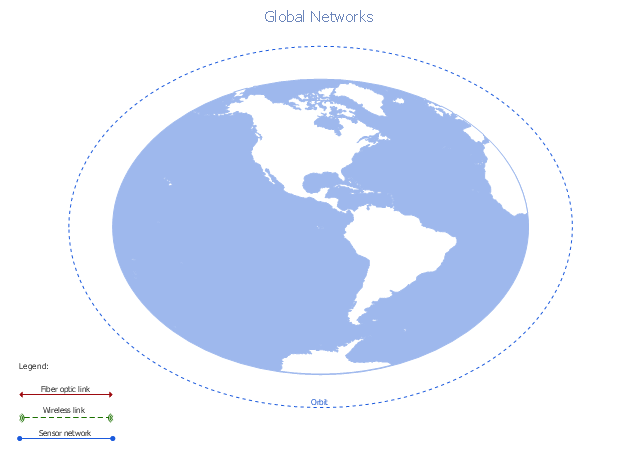
The vector stencils library "Global networks" contains 63 symbols for drawing the global network diagrams using the ConceptDraw PRO diagramming and vector drawing software.
The example "Design elements - Global networks" is included in the Vehicular Networking solution from the Computer and Networks area of ConceptDraw Solution Park.
Communication capabilities in vehicles are the basis of an envisioned InVANET or intelligent transportation systems (ITS). Vehicles are enabled to communicate among themselves (vehicle-to-vehicle, V2V) and via roadside access points (vehicle-to-roadside, V2R) also called as Road Side Units (RSUs). Vehicular communication is expected to contribute to safer and more efficient roads by providing timely information to drivers, and also to make travel more convenient. The integration of V2V and V2R communication is beneficial because V2R provides better service sparse networks and long distance communication, whereas V2V enables direct communication for small to medium distances/ areas and at locations where roadside access points are not available." [Intelligent vehicular ad-hoc network. Wikipedia]
The vector stencils library "Global networks" contains 63 symbols for drawing the global network diagrams using the ConceptDraw PRO diagramming and vector drawing software.
The example "Design elements - Global networks" is included in the Vehicular Networking solution from the Computer and Networks area of ConceptDraw Solution Park.
Vehicle network symbols
 Jackson Structured Programming (JSP) Diagrams
The Jackson Structured Programming (JSP) Diagram solution extends the functionality and drawing abilities of the ConceptDraw DIAGRAM software with set of illustrative JSP diagrams samples and large variety of predesigned vector objects of actions, processes, procedures, selection, iteration, as well as arrows and connectors to join the objects during Jackson structured development and designing Jackson structured programming diagrams, JSP diagram, Jackson structure diagram (JSD), Program structure diagram. The powerful abilities of this solution make the ConceptDraw DIAGRAM ideal assistant for programmers, software developers, structural programmers, computer engineers, applications constructors, designers, specialists in structured programming and Jackson systems design, and other technical, computer and software specialists.
 Wireless Networks
The Wireless Networks Solution extends ConceptDraw DIAGRAM software with professional diagramming tools, set of wireless network diagram templates and samples, comprehensive library of wireless communications and WLAN objects to help network engineers and designers efficiently design and create Wireless network diagrams that illustrate wireless networks of any speed and complexity, and help to identify all required equipment for construction and updating wireless networks, and calculating their costs.
- Intelligent transportation system | Vehicular Networking | Systems ...
- Intelligent transportation system | Global vehicular network diagram ...
- The Diagram Of Transportation System
- Intelligent transportation system | Entity-Relationship Diagram (ERD ...
- Intelligent transportation system | Fishbone Diagrams | Automatic ...
- Intelligent transportation system | Vehicular Networking | Global ...
- Intelligent transportation system | Computer Network Diagrams ...
- Domain Diagram For Transport Management System
- UML Class Diagram Example for Transport System
- UML Class Diagram Example for Transport System