Process Flow Diagram Symbols

The vector stencils library "Pumps" contains 82 symbols of pumps, compressors, fans, turbines, and power generators.
Use these icons to design pumping systems, air and fluid compression systems, and industrial process diagrams.
"A pump is a device that moves fluids (liquids or gases), or sometimes slurries, by mechanical action. Pumps can be classified into three major groups according to the method they use to move the fluid: direct lift, displacement, and gravity pumps.
Pumps operate by some mechanism (typically reciprocating or rotary), and consume energy to perform mechanical work by moving the fluid. Pumps operate via many energy sources, including manual operation, electricity, engines, or wind power, come in many sizes, from microscopic for use in medical applications to large industrial pumps.
Mechanical pumps serve in a wide range of applications such as pumping water from wells, aquarium filtering, pond filtering and aeration, in the car industry for water-cooling and fuel injection, in the energy industry for pumping oil and natural gas or for operating cooling towers. In the medical industry, pumps are used for biochemical processes in developing and manufacturing medicine, and as artificial replacements for body parts, in particular the artificial heart and penile prosthesis.
In biology, many different types of chemical and bio-mechanical pumps have evolved, and biomimicry is sometimes used in developing new types of mechanical pumps." [Pump. Wikipedia]
The example "Design elements - Pumps" was created using the ConceptDraw PRO diagramming and vector drawing software extended with the Chemical and Process Engineering solution from the Engineering area of ConceptDraw Solution Park.
Pump symbols

The vector stencils library "Pumps" contains 82 symbols of pumps, compressors, fans, turbines, and power generators.
Use these icons to design pumping systems, air and fluid compression systems, and industrial process diagrams in the ConceptDraw PRO software extended with the Chemical and Process Engineering solution from the Chemical and Process Engineering area of ConceptDraw Solution Park.
www.conceptdraw.com/ solution-park/ engineering-chemical-process
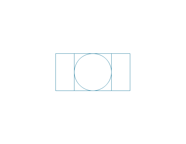
In-line pump

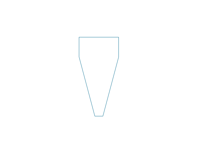
In-line pump 2

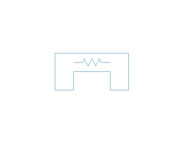
Positive displacement

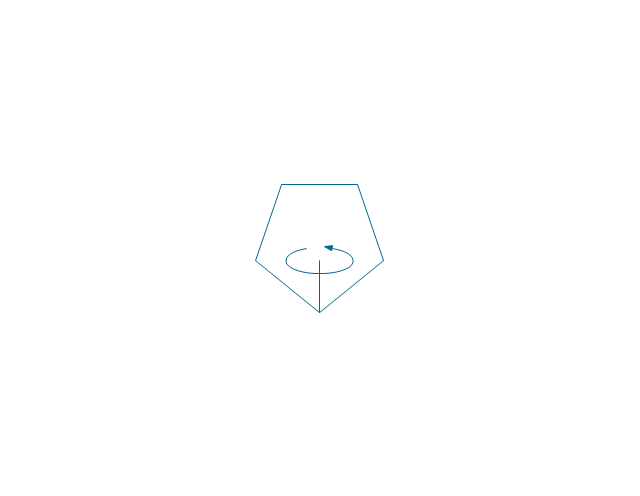
Centrifugal pump (arrows)
-pumps---vector-stencils-library.png--diagram-flowchart-example.png)
Centrifugal pump

Rotary pump 1

Rotary pump 2

Proportioning pump

Pump vacuum

Pump positive displacement

Pump piston

Pump liquid ring

Pump oil-sealed rotary (single)
-pumps---vector-stencils-library.png--diagram-flowchart-example.png)
Pump oil-sealed rotary (multi)
-pumps---vector-stencils-library.png--diagram-flowchart-example.png)
Pump roots

Pump gas ballast

Pump turbo molecular

Pump general

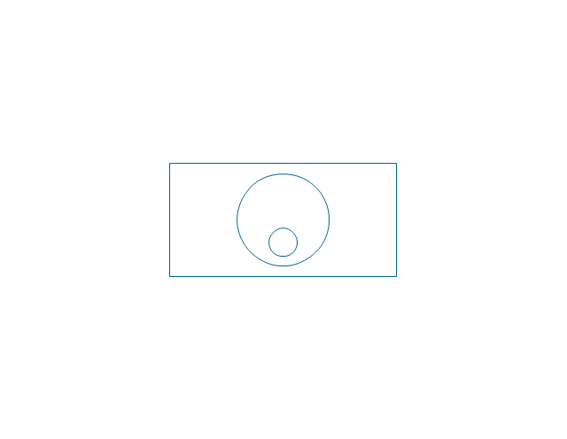
Pump centrifugal

Pump positive displacement 2

Pump gear

Pump screw

Pump helical rotor

Pump reciprocating

Pump diaphragm

Pump liquid jet

Pump centrifugal 2

Pump diaphragm 2

Pump gear 2

Pump general 2

Pump helical rotor 2

Pump reciprocating 2

Pump screw 2

Compressor general

Compressor container

Compressor rotary

Compressor screw

Compressor reciprocating

Compressor ejector

Compressor general 2

Compressor liquid ring

Compressor positive displacement

Compressor reciprocating 2

Compressor reciprocating diaphragm

Compressor roller vane

Compressor rotary 2

Compressor screw 2

Compressor turbo

Compressor general 3

Compressor reciprocating 3

Compressor reciprocating diaphragm 2

Compressor roller vane 2

Compressor rotary 3

Compressor screw 3

Rotary compressor

Motor driven turbine

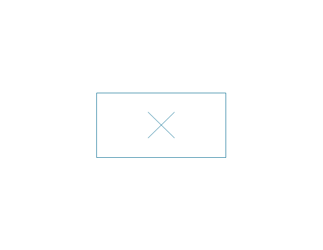
Compressor (center line)
-pumps---vector-stencils-library.png--diagram-flowchart-example.png)
Compressor

Turbine

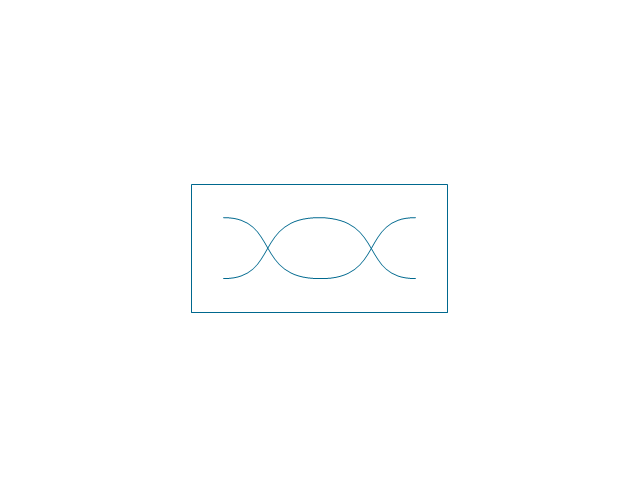
Turbine (center line)
-pumps---vector-stencils-library.png--diagram-flowchart-example.png)
Reciprocating pump/compressor

Reciprocating pump 2

Fan general

Fan radial

Fan axial

Fan general 2

Fan radial 2

Fan axial 2

Centrifugal fan 2 (center circle)
-pumps---vector-stencils-library.png--diagram-flowchart-example.png)
Centrifugal fan

Axial flow fan supply

Axial flow fan exhaust

Axial flow fan exhaust wall-type

Axial flow fan supply wall-type

Axial flow fan 2

Ejector / injector

Spray

Shower

Fan blades horizontal

Fan blades vertical

Fan blades (4)
-pumps---vector-stencils-library.png--diagram-flowchart-example.png)
Triple fan blades

Mechanical Drawing Symbols

The vector stencils library "Industrial equipment" contains 81 symbols of pumps, compressors, fans, turbines, and power generators.
Use these shapes to design pumping systems, air and fluid compression systems, and industrial process diagrams in the ConceptDraw PRO software extended with the Chemical and Process Engineering solution from the Chemical and Process Engineering area of ConceptDraw Solution Park.
www.conceptdraw.com/ solution-park/ engineering-chemical-process
Breaker
Crusher
Crusher coarse
Crusher medium
Crusher fine
Roll crusher
Hammer crusher

Crusher single load
Crusher hammer

Crusher impact
Crusher jaw

Crusher high-speed roller
Crusher cone

Crusher cone 2
Crusher general
Crusher hammer 2
Crusher impact 2
Crusher jaw 2
Crusher roller
Ball mill

Mill general
Mill hammer
Mill impact
Mill jet
Mill roller
Mill vibrator
Mixer
Mixer general
Mixer rotary
Mixer can
Mixer fluidized

Kneader
Kneader general
Kneader wheel
Kneader ball
Kneader rolling
Kneader blade
Blender
Double blender
Fluid separator general
Fluid separator wet

Fluid separator dry
Fluid separator gravitation
Fluid separator inertial

Fluid separator centrifugal
Filter 1
Filter 2

Rotary filter

Screen

Electromagnet
Cyclone 1
Cyclone 2
Centrifuge general
Centrifuge dehydrator
Centrifuge submersion
Centrifuge 2
Briquetting machine standard
Briquetting machine

Prill tower
Dryer
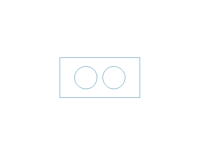
Conveyor 2 circles 2 lines
Conveyor 2 circles 1 line
Conveyor 1 circle 2 lines
Conveyor 1 circle 1 line
Conveyor wheel

Boom loader
Scraper conveyor
Screw conveyor
Screw conveyor 2
Elevator 1
Elevator 2
Skip hoist
Overhead conveyor
Overhead conveyor with hooks
Overhead conveyor with buckets
Hoist
Hoist with hook
Hoist with grab
Electric motor
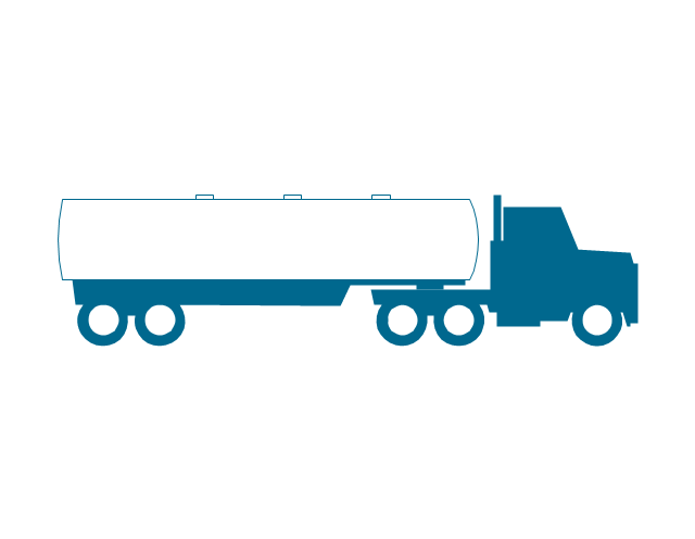
Tank truck
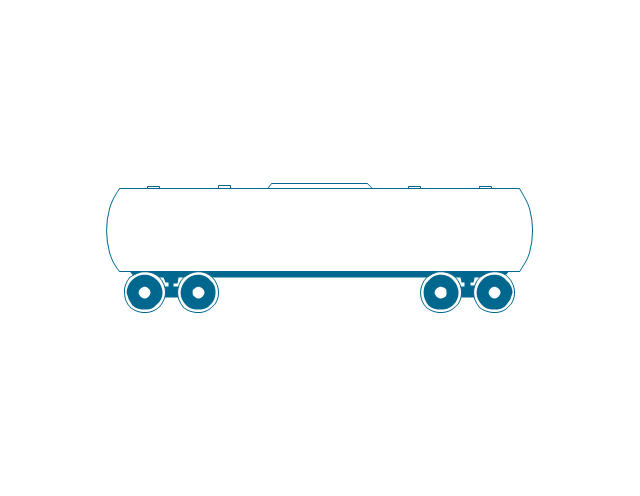
Tank car
Flowchart Components

Electrical Drawing Software and Electrical Symbols

The vector stencils library "Valves and fittings" contains 104 symbols of valve components.
Use these icons for drawing industrial piping systems; process, vacuum, and fluids piping; hydraulics piping; air and gas piping; materials distribution; and liquid transfer systems.
"A valve is a device that regulates, directs or controls the flow of a fluid (gases, liquids, fluidized solids, or slurries) by opening, closing, or partially obstructing various passageways. Valves are technically valves fittings, but are usually discussed as a separate category. In an open valve, fluid flows in a direction from higher pressure to lower pressure.
The simplest, and very ancient, valve is simply a freely hinged flap which drops to obstruct fluid (gas or liquid) flow in one direction, but is pushed open by flow in the opposite direction. This is called a check valve, as it prevents or "checks" the flow in one direction. ...
Valves are found in virtually every industrial process, including water & sewage processing, mining, power generation, processing of oil, gas & petroleum, food manufacturing, chemical & plastic manufacturing and many other fields. ...
Valves may be operated manually, either by a handle, lever, pedal or wheel. Valves may also be automatic, driven by changes in pressure, temperature, or flow. These changes may act upon a diaphragm or a piston which in turn activates the valve, examples of this type of valve found commonly are safety valves fitted to hot water systems or boilers.
More complex control systems using valves requiring automatic control based on an external input (i.e., regulating flow through a pipe to a changing set point) require an actuator. An actuator will stroke the valve depending on its input and set-up, allowing the valve to be positioned accurately, and allowing control over a variety of requirements." [Valve. Wikipedia]
The example "Design elements - Valves and fittings" was created using the ConceptDraw PRO diagramming and vector drawing software extended with the Chemical and Process Engineering solution from the Engineering area of ConceptDraw Solution Park.
Valves and fittings symbols

Electrical Symbols — Inductors

Interior Design. Piping Plan — Design Elements

- Design elements - Pumps | Ecology pictograms - Vector stencils ...
- Symbol For Pump And Turbine
- Symbol Water Pump
- Symbol Rotary Pump
- Pump Diagram Symbol
- Design elements - Pumps | Design elements - Chemical ...
- Wind Png Icons
- Design elements - Pumps | Design elements - Ports and Flows ...
- Design elements - Pumps | Pumps - Vector stencils library ...
- Pumps - Vector stencils library | Design elements - Pumps | HVAC ...