IDEF0 standard with ConceptDraw DIAGRAM

 IDEF0 Diagrams
IDEF0 Diagrams visualize system models using the Integration Definition for Function Modeling (IDEF) methodology. Use them for analysis, development and integration of information and software systems, and business process modelling.
IDEF0 Visio

IDEF3 Standard

HelpDesk
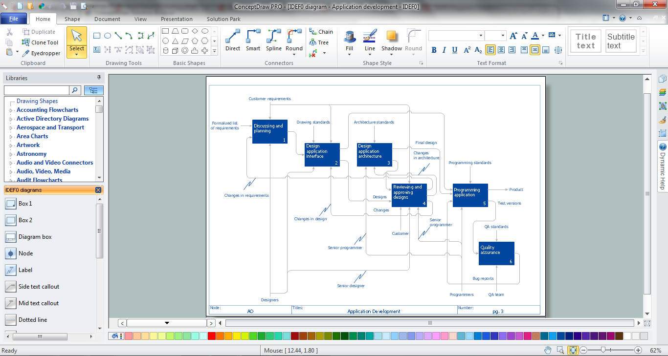
How to Create an IDEF0 Diagram for an Application Development

IDEF0 Diagram

IDEF0 Flowchart Symbols

HelpDesk
How to Create an IDEF0 Diagram

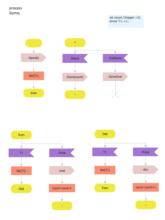
SDL Diagram
IDEF0 Software
- Create Idef0 Diagrams Online
- IDEF0 Diagrams | IDEF3 Standard | ConceptDraw Solution Park ...
- IDEF0 Diagrams | IDEF0 Visio | UML Component Diagram Example ...
- Data Flow Diagrams (DFD) | IDEF0 Diagrams | UML Component ...
- IDEF0 Diagrams | Level 0 Dfd Diagram For Online Shopping
- How to Create an IDEF0 Diagram for an Application Development ...
- IDEF0 Diagrams | Online Shopping Dfd 0 One Level
- IDEF0 Diagrams | Software development with ConceptDraw ...
- IDEF0 Diagrams | IDEF3 Standard | Idef0 Shop Example
- IDEF0 Diagrams | Online Shopping Context Level Diagram