 IDEF0 Diagrams
IDEF0 Diagrams visualize system models using the Integration Definition for Function Modeling (IDEF) methodology. Use them for analysis, development and integration of information and software systems, and business process modelling. Having the IDEF0 Diagrams solution as well may lead to getting the professionally-looking drawings based on the pre-made samples and templates from solution. There is also a stencil library with the IDEF0-related design elements that can be taken from this solution in order to draw the IDEF0 diagrams.
HelpDesk
How to Create an IDEF0 Diagram

HelpDesk
How to Create an IDEF0 Diagram for an Application Development

IDEF0 Flowchart Symbols

IDEF0 Diagram

This IDEF0 diagram sample was created on the base of the figure from the website of the Engineering Laboratory of the National Institute of Standards and Technology (NIST). [mel.nist.gov/ msidlibrary/ doc/ kc_ morris/ gsa-final_ files/ image011.gif]
"Verification and Validation of Computer Simulation Models is conducted during the development of a simulation model with the ultimate goal of producing an accurate and credible model.
"Simulation models are increasingly being used to solve problems and to aid in decision-making. The developers and users of these models, the decision makers using information obtained from the results of these models, and the individuals affected by decisions based on such models are all rightly concerned with whether a model and its results are “correct”". This concern is addressed through verification and validation of the simulation model.
Simulation models are approximate imitations of real-world systems and they never exactly imitate the real-world system. Due to that, a model should be verified and validated to the degree needed for the models intended purpose or application.
The verification and validation of simulation model starts after functional specifications have been documented and initial model development has been completed. Verification and validation is an iterative process that takes place throughout the development of a model." [Verification and Validation of Computer Simulation Models. Wikipedia]
The IDEF0 diagram example "Model validation" was created using the ConceptDraw PRO diagramming and vector drawing software extended with the IDEF0 Diagrams solution from the Software Development area of ConceptDraw Solution Park.
IDEF0 diagram
The vector stencils library "IDEF0 diagrams" contains 18 symbols for drawing IDEF0 function modeling diagrams using the ConceptDraw PRO diagramming and vector drawing software.
"The IDEF0 model ... is based on a simple syntax. Each activity is described by a verb-based label placed in a box. Inputs are shown as arrows entering the left side of the activity box while output are shown as exiting arrows on the right side of the box. Controls are displayed as arrows entering the top of the box and mechanisms are displayed as arrows entering from the bottom of the box. Inputs, Controls, Outputs, and Mechanisms are all referred to as concepts.
- Arrow : A directed line, composed of one or more arrow segments, that models an open channel or conduit conveying data or objects from source (no arrowhead) to use (with arrowhead). There are 4 arrow classes: Input Arrow, Output Arrow, Control Arrow, and Mechanism Arrow (includes Call Arrow). See Arrow Segment, Boundary Arrow, Internal Arrow.
- Box : A rectangle, containing a name and number, used to represent a function.
- Context : The immediate environment in which a function (or set of functions on a diagram) operates.
- Decomposition : The partitioning of a modeled function into its component functions.
- Fork : The junction at which an IDEF0 arrow segment (going from source to use) divides into two or more arrow segments. May denote unbundling of meaning.
- Function : An activity, process, or transformation (modeled by an IDEF0 box) identified by a verb or verb phrase that describes what must be accomplished.
- Join : The junction at which an IDEF0 arrow segment (going from source to use) merges with one or more other arrow segments to form a single arrow segment. May denote bundling of arrow segment meanings.
- Node : A box from which child boxes originate; a parent box. See Node Index, Node Tree, Node Number, Node Reference, Diagram Node Number." [IDEF0. Wikipedia]
The example "Design elements - IDEF0 diagram" is included in the IDEF0 Diagrams solution from the Software Development area of ConceptDraw Solution Park.
IDEF0 symbols

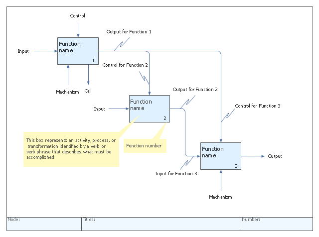
"IDEF0, a compound acronym (Icam DEFinition for Function Modeling, where 'ICAM' is an acronym for Integrated Computer Aided Manufacturing) is a function modeling methodology for describing manufacturing functions, which offers a functional modeling language for the analysis, development, reengineering, and integration of information systems; business processes; or software engineering analysis.
IDEF0 is part of the IDEF family of modeling languages in the field of software engineering, and is built on the functional modeling language Structured Analysis and Design Technique (SADT). ...
FIPS PUB 183 "Integration Definition for Function Modeling (IDEF0)," was withdrawn as a Federal Standard (in favor of OPEN Specifications and Standards) September 2, 2008, as cited in "The Federal Register", Volume 73, page 51276 (73FR/ 51276). ...
IDEF0, used to produce a "function model". A function model is a structured representation of the functions, activities or processes within the modeled system or subject area." [IDEF0. Wikipedia]
The template "IDEF0 diagram" is included in the IDEF0 Diagrams solution from the Software Development area of ConceptDraw Solution Park.
IDEF0 template
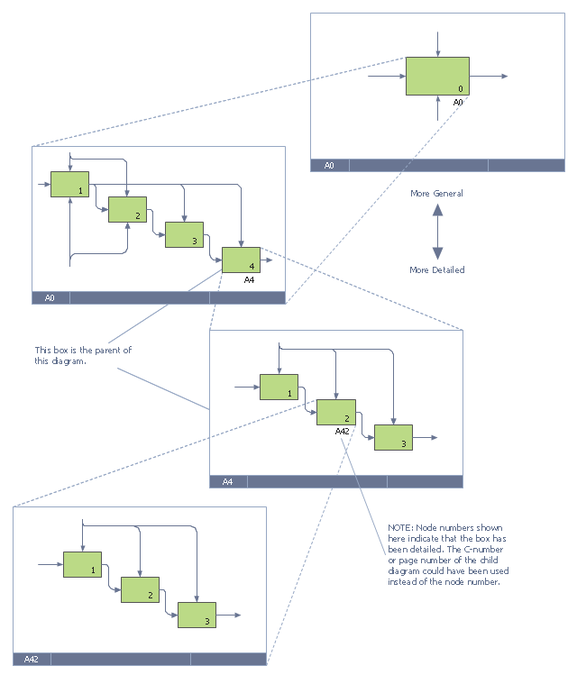
This IDEF0 diagram example was redesigned from the Wikimedia Commons file: 6 Decomposition Structure.svg.
[commons.wikimedia.org/ wiki/ File:6_ Decomposition_ Structure.svg]
"Functional decomposition refers broadly to the process of resolving a functional relationship into its constituent parts in such a way that the original function can be reconstructed (i.e., recomposed) from those parts by function composition. In general, this process of decomposition is undertaken either for the purpose of gaining insight into the identity of the constituent components (which may reflect individual physical processes of interest, for example), or for the purpose of obtaining a compressed representation of the global function, a task which is feasible only when the constituent processes possess a certain level of modularity (i.e., independence or non-interaction). Interactions between the components are critical to the function of the collection. All interactions may not be observable, but possibly deduced through repetitive perception, synthesis, validation and verification of composite behavior." [Functional decomposition. Wikipedia]
The example "IDEF0 diagram - Decomposition structure" was created using the ConceptDraw PRO diagramming and vector drawing software extended with the solution "IDEF Business Process Diagrams" from the area "Business Processes" of ConceptDraw Solution Park.
IDEF0 business process diagram
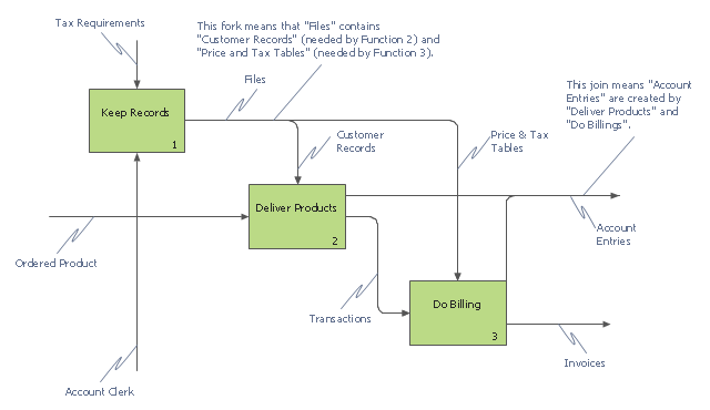
This IDEF0 diagram example was redesigned from the Wikimedia Commons file: 12 Connections Between Boxes.svg.
[commons.wikimedia.org/ wiki/ File:12_ Connections_ Between_ Boxes.svg]
"Graphical notation.
IDEF0 is a model that consists of a hierarchical series of diagrams, text, and glossary cross referenced to each other. The two primary modeling components are:
- functions (represented on a diagram by boxes), and
- data and objects that interrelate those functions (represented by arrows).
.... the position at which the arrow attaches to a box conveys the specific role of the interface. The controls enter the top of the box. The inputs, the data or objects acted upon by the operation, enter the box from the left. The outputs of the operation leave the right-hand side of the box. Mechanism arrows that provide supporting means for performing the function join (point up to) the bottom of the box." [IDEF0. Wikipedia]
The example "IDEF0 diagram - Inter-box connections" was created using the ConceptDraw PRO diagramming and vector drawing software extended with the solution "IDEF Business Process Diagrams" from the area "Business Processes" of ConceptDraw Solution Park.
IDEF0 business process diagram
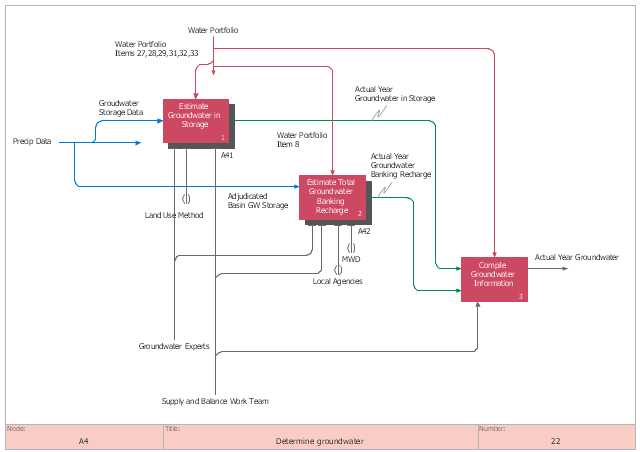
This IDEF0 diagram sample was created on the base of the figure from the California Water Plan website. [waterplan.water.ca.gov/ technical/ cwpu2009/ flowdiaghtml/ dgm18.htm]
"The California Water Plan provides a collaborative planning framework for elected officials, agencies, tribes, water and resource managers, businesses, academia, stakeholders, and the public to develop findings and recommendations and make informed decisions for California's water future. The plan, updated every five years, presents the status and trends of California's water-dependent natural resources; water supplies; and agricultural, urban, and environmental water demands for a range of plausible future scenarios. The California Water Plan also evaluates different combinations of regional and statewide resource management strategies to reduce water demand, increase water supply, reduce flood risk, improve water quality, and enhance environmental and resource stewardship. The evaluations and assessments performed for the plan help identify effective actions and policies for meeting California's resource management objectives in the near term and for several decades to come." [waterplan.water.ca.gov]
The IDEF0 diagram example "Determine groundwater" was created using the ConceptDraw PRO diagramming and vector drawing software extended with the IDEF0 Diagrams solution from the Software Development area of ConceptDraw Solution Park.
IDEF0 diagram
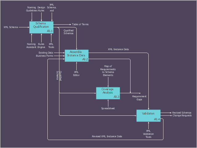
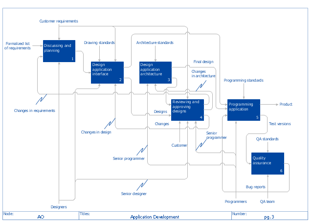
"The IDEF0 Functional Modeling method is designed to model the decisions, actions, and activities of an organization or system. ...
IDEF0 includes both a definition of a graphical modeling language (syntax and semantics) and a description of a comprehensive methodology for developing models. ...
IDEF0 is used to show data flow, system control, and the functional flow of lifecycle processes. IDEF0 is capable of graphically representing a wide variety of business, manufacturing and other types of enterprise operations to any level of detail. It provides rigorous and precise description, and promotes consistency of usage and interpretation." [IDEF0. Wikipedia]
The IDEF0 diagram example "Application development" was created using the ConceptDraw PRO diagramming and vector drawing software extended with the IDEF0 Diagrams solution from the Software Development area of ConceptDraw Solution Park.
IDEF0 diagram example
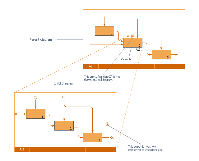
This IDEF0 diagram was redesigned from the Wikimedia Commons file: 18 Example of Tunneled Arrows.svg.
[commons.wikimedia.org/ wiki/ File:18_ Example_ of_ Tunneled_ Arrows.svg]
"Tunneled Arrows.
Arrows that provide information at one level of decomposition but are not needed at another (parent, child) level." [classes.engr.oregonstate.edu/ mime/ fall2013/ ie545-001/ Slides/ class%20 01-3b%20 IDEF0%20 1%20 revised.pdf]
The example "IDEF0 diagram - Tunneled arrows" was created using the ConceptDraw PRO diagramming and vector drawing software extended with the solution "IDEF Business Process Diagrams" from the area "Business Processes" of ConceptDraw Solution Park.
IDEF0 business process diagram
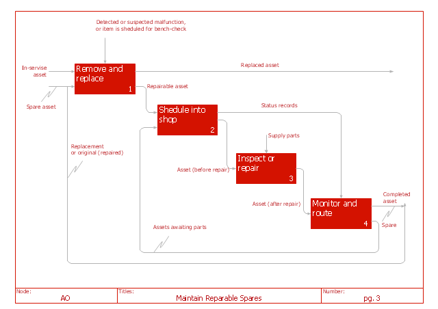
"IDEF0 may be used to model a wide variety of automated and non-automated systems. For new systems, it may be used first to define the requirements and specify the functions, and then to design an implementation that meets the requirements and performs the functions. For existing systems, IDEF0 can be used to analyze the functions the system performs and to record the mechanisms (means) by which these are done. The result of applying IDEF0 to a system is a model that consists of a hierarchical series of diagrams, text, and glossary cross-referenced to each other. The two primary modeling components are functions (represented on a diagram by boxes) and the data and objects that inter-relate those functions (represented by arrows)." [IDEF0. Wikipedia]
The IDEF0 diagram example "Maintain reparable spares" was created using the ConceptDraw PRO diagramming and vector drawing software extended with the IDEF0 Diagrams solution from the Software Development area of ConceptDraw Solution Park.
The IDEF0 diagram example "Maintain reparable spares" was created using the ConceptDraw PRO diagramming and vector drawing software extended with the IDEF0 Diagrams solution from the Software Development area of ConceptDraw Solution Park.
IDEF0 diagram
This IDEF0 diagram sample was created on the base of the figure from the website of the Engineering Laboratory of the National Institute of Standards and Technology (NIST). [mel.nist.gov/ msidlibrary/ doc/ kc_ morris/ gsa-final_ files/ image002.gif]
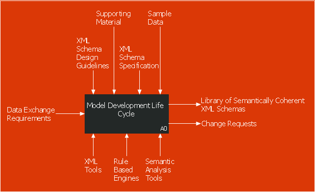
"The systems development life cycle (SDLC), also referred to as the application development life-cycle, is a term used in systems engineering, information systems and software engineering to describe a process for planning, creating, testing, and deploying an information system. The systems development life-cycle concept applies to a range of hardware and software configurations, as a system can be composed of hardware only, software only, or a combination of both." [Systems development life cycle. Wikipedia]
The IDEF0 diagram example "Model development life cycle" was created using the ConceptDraw PRO diagramming and vector drawing software extended with the IDEF0 Diagrams solution from the Software Development area of ConceptDraw Solution Park.
IDEF0 diagram
This IDEF0 diagram sample was created on the base of the figure from the website of the Engineering Laboratory of the National Institute of Standards and Technology (NIST). [mel.nist.gov/ msidlibrary/ doc/ kc_ morris/ gsa-final_ files/ image017.gif]
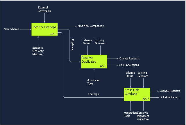
"Model integration is the technology that binds disparate modelling efforts together with the aim to produce a more representative, and therefore more accurate, simulation of the target system. ...
The concept of model integration is central to all systems modelling communities. In complex systems research, where the modelling community often employs a sizeable variety of modelling methodologies, the need for such a model integration technology is vital to understanding the very systems they endeavour to understand." [scs.org/ magazines/ 2011-01/ index_ file/ Files/ Patel_ ED(2).pdf]
The IDEF0 diagram example "Model integration" was created using the ConceptDraw PRO diagramming and vector drawing software extended with the IDEF0 Diagrams solution from the Software Development area of ConceptDraw Solution Park.
IDEF0 diagram
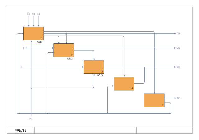
This IDEF0 diagram example was redesigned from the Wikimedia Commons file: 7 Detail Reference Expression Use.svg.
[commons.wikimedia.org/ wiki/ File:7_ Detail_ Reference_ Expression_ Use.svg]
The example "IDEF0 diagram - Detail reference expression use" was created using the ConceptDraw PRO diagramming and vector drawing software extended with the solution "IDEF Business Process Diagrams" from the area "Business Processes" of ConceptDraw Solution Park.
IDEF0 diagram example
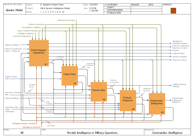
This IDEF0 diagram example was redesigned from the Wikimedia Commons file: C4ISR Architecture Framework, Example Activity Diagram in IDEF0 Format.jpg. [commons.wikimedia.org/ wiki/ File:C4ISR_ Architecture_ Framework,_ Example_ Activity_ Diagram_ in_ IDEF0_ Format.jpg]
"... the C4ISR concept of Command, Control, Communications, Computers, Intelligence, Surveillance and Reconnaissance ..." [en.wikipedia.org/ wiki/ C4ISR]
"The C4ISR Architectural Framework (C4ISR AF) is now known as DoDAF, is a reference model developed by the US Department of Defense in the 1990s." [commons.wikimedia.org/ wiki/ Category:C4ISR_ Architecture_ Framework]
"The Department of Defense Architecture Framework (DoDAF) is an architecture framework for the United States Department of Defense (DoD) that provides visualization infrastructure for specific stakeholders concerns through viewpoints organized by various views. These views are artifacts for visualizing, understanding, and assimilating the broad scope and complexities of an architecture description through tabular, structural, behavioral, ontological, pictorial, temporal, graphical, probabilistic, or alternative conceptual means.
This Architecture Framework is especially suited to large systems with complex integration and interoperability challenges, and it is apparently unique in its employment of "operational views". These views offer overview and details aimed to specific stakeholders within their domain and in interaction with other domains in which the system will operate." [en.wikipedia.org/ wiki/ Department_ of_ Defense_ Architecture_ Framework]
The example "C4ISR architecture framework - IDEF0 activity diagram" was created using the ConceptDraw PRO diagramming and vector drawing software extended with the solution "IDEF Business Process Diagrams" from the area "Business Processes" of ConceptDraw Solution Park.
IDEF0 business process diagram
Used Solutions
IDEF0 Software

IDEF0 standard with ConceptDraw DIAGRAM

- How to Create an IDEF0 Diagram for an Application Development ...
- IDEF0 Software | How to Create an IDEF0 Diagram for an ...
- IDEF0 diagram template | Software Diagram Templates | IDEF0 ...
- How to Create an IDEF0 Diagram for an Application Development
- IDEF0 Visio | How to Create an IDEF0 Diagram for an Application ...
- IDEF0 Software | IDEF0 standard with ConceptDraw PRO | IDEF0 ...
- IDEF0 Visio | How to Create an IDEF0 Diagram for an Application ...
- IDEF Business Process Diagrams | IDEF3 Standard | IDEF0 Visio ...
- IDEF0 Diagrams | IDEF Business Process Diagrams | Application ...
- IDEF0 diagram template | How to Create an IDEF0 Diagram for an ...