Cisco Switches and Hubs. Cisco icons, shapes, stencils and symbols

Cisco WAN. Cisco icons, shapes, stencils and symbols

Cisco Products Additional. Cisco icons, shapes, stencils and symbols

Network Hubs


The vector stencils library "Wireless networks" contains 82 icon symbols for drawing wireless computer network diagrams and equipment layout plans.
"A wireless network is any type of computer network that uses wireless data connections for connecting network nodes.
Wireless networking is a method by which homes, telecommunications networks and enterprise (business) installations avoid the costly process of introducing cables into a building, or as a connection between various equipment locations.
Wireless telecommunications networks are generally implemented and administered using radio communication. This implementation takes place at the physical level (layer) of the OSI model network structure.
Examples of wireless networks include cell phone networks, Wi-Fi local networks and terrestrial microwave networks." [Wireless network. Wikipedia]
The clip art example "Wireless networks - Vector stencils library" was created using the ConceptDraw PRO diagramming and vector drawing software extended with the Wireless Networks solution from the Computer and Networks area of ConceptDraw Solution Park.
www.conceptdraw.com/ solution-park/ wireless-networks
Building 1
Building 4
Coverage (Blue)
-wireless-networks---vector-stencils-library.png--diagram-flowchart-example.png)
Wireless Connectivity

Network Cloud
Cloud
Wi-Fi Access

Tree

Computer
Laptop Computer

Server
Wireless Network Storage
Router
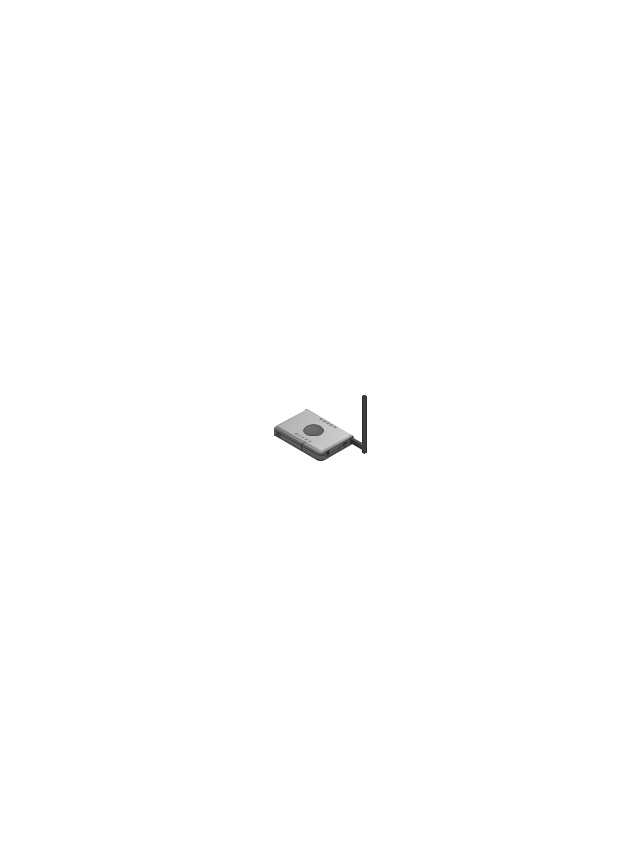
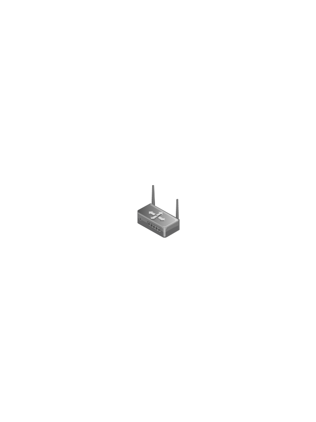
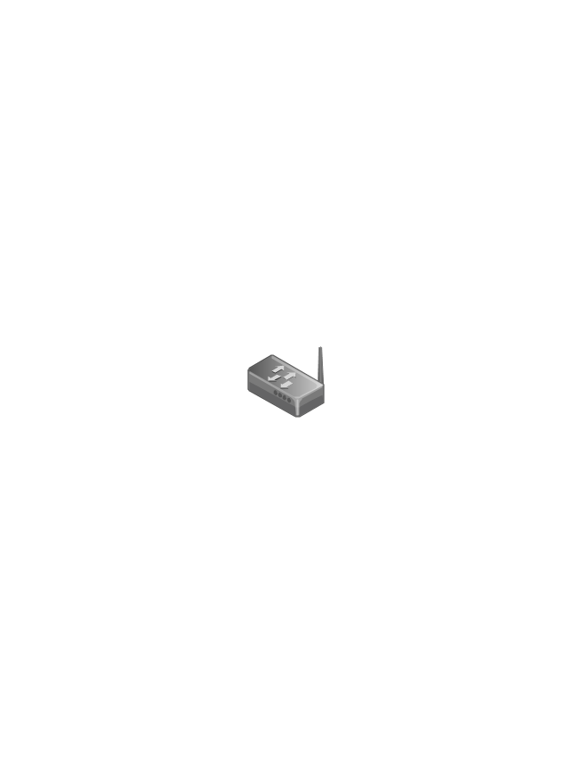
Wireless Router
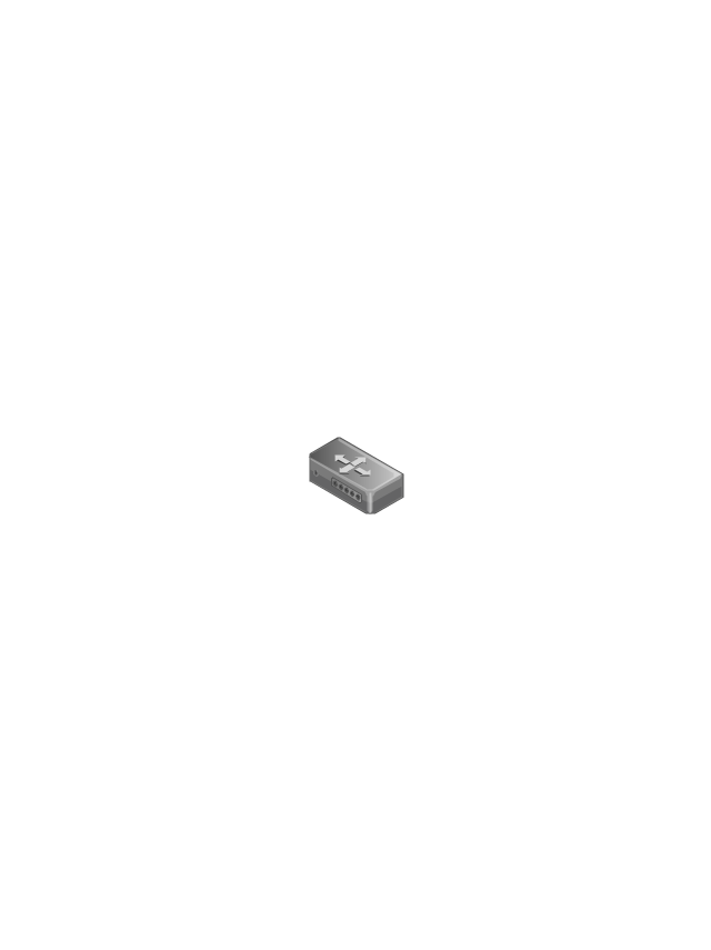
Switch
Wireless Access Point
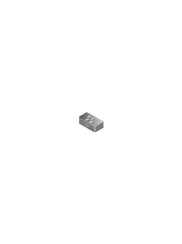
1U Hub Switch

2U Hub Switch
1U Server

2U Server

3U Server

4U Server

Outdoor Access Point
Indoor Access Point

Outdoor Wi-Fi Access Point

Access Point

Outdoor Mesh Node
Outdoor Mesh Node
Outdoor Access Node
Outdoor Access Node

Base Station
Cellular Phone

Outdoor Mesh Node
Active Directory Server
Smart WLAN Controller

Smart WLAN Controller

Smart Wi-Fi Access Point
Indoor Wi-Fi Access Point

Firewall
Coverage (Yellow)
-wireless-networks---vector-stencils-library.png--diagram-flowchart-example.png)
Coverage (O-Shaped)
-wireless-networks---vector-stencils-library.png--diagram-flowchart-example.png)
Outdoor Mesh Node
Network Topologies


Cisco Network Templates

Network Topology Mapper
Wireless Network Topology

The vector stencils library "Cisco switches and hubs" contains 26 symbols of Cisco switches and hubs for drawing computer network diagrams.
"A switch is a device used on a computer network to physically connect devices together. Multiple cables can be connected to a switch to enable networked devices to communicate with each other. Switches manage the flow of data across a network by only transmitting a received message to the device for which the message was intended. Each networked device connected to a switch can be identified using a MAC address, allowing the switch to regulate the flow of traffic. This maximises security and efficiency of the network. Because of these features, a switch is often considered more "intelligent" than a network hub. Hubs neither provide security, or identification of connected devices. This means that messages have to be transmitted out of every port of the hub, greatly degrading the efficiency of the network." [Network switch. Wikipedia]
"An Ethernet hub, active hub, network hub, repeater hub, multiport repeater or hub is a device for connecting multiple Ethernet devices together and making them act as a single network segment. It has multiple input/ output (I/ O) ports, in which a signal introduced at the input of any port appears at the output of every port except the original incoming. A hub works at the physical layer (layer 1) of the OSI model. The device is a form of multiport repeater. Repeater hubs also participate in collision detection, forwarding a jam signal to all ports if it detects a collision." [Ethernet hub. Wikipedia]
The symbols example "Cisco switches and hubs - Vector stencils library" was created using the ConceptDraw PRO diagramming and vector drawing software extended with the Cisco Network Diagrams solution from the Computer and Networks area of ConceptDraw Solution Park.
www.conceptdraw.com/ solution-park/ computer-networks-cisco
Cisco hub

100BaseT hub

Small hub

Workgroup switch

Workgroup switch, subdued

Voice-enabled workgroup switch

ATM switch

LAN2LAN switch

ISDN switch

MGX 8000 multiservice switch

Multilayer switch with Si

Multilayer switch

Multilayer switch with Si, subdued

Program switch

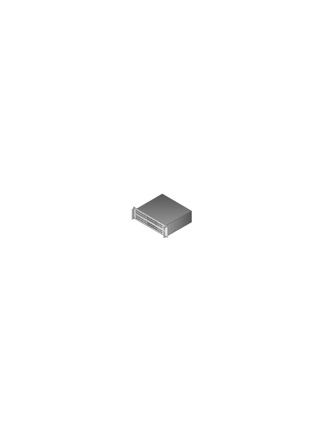
Data center switch

Voice-enabled ATM switch

IP DSL switch

Content switch

Content service switch 1100

Virtual layer switch

Layer 2 remote switch

Server switch

Multilayer remote switch

Multifabric server switch

Access gateway

Long-Reach CPE

Network Glossary Definition

The vector stencils library "Network layout floorplan" contain 34 symbol icons for drawing computer network floor plans, communication equipment layouts, and structured cabling diagrams.
"Structured cabling is building or campus telecommunications cabling infrastructure that consists of a number of standardized smaller elements (hence structured) called subsystems. ...
Structured cabling design and installation is governed by a set of standards that specify wiring data centers, offices, and apartment buildings for data or voice communications using various kinds of cable, most commonly category 5e (CAT-5e), category 6 (CAT-6), and fibre optic cabling and modular connectors. These standards define how to lay the cabling in various topologies in order to meet the needs of the customer, typically using a central patch panel (which is normally 19 inch rack-mounted), from where each modular connection can be used as needed. Each outlet is then patched into a network switch (normally also rack-mounted) for network use or into an IP or PBX (private branch exchange) telephone system patch panel." [Structured cabling. Wikipedia]
The design elements example "Network layout floorplan - Vector stencils library" was created using the ConceptDraw PRO diagramming and vector drawing software extended with the Network Layout Floor Plans solution from the Computer and Networks area of ConceptDraw Solution Park.
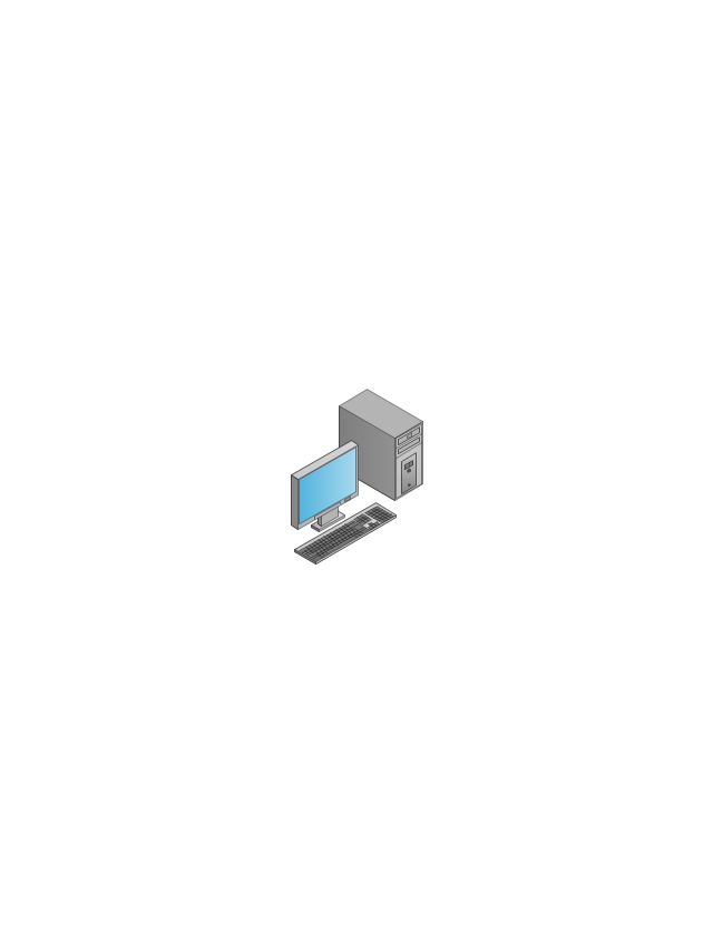
PC

Scanner

Switch

Router

Modem

Hub

Rack Mount

Printer

Floor Mounted Outlet

Single Outlet

Duplex Outlet

Direct bus cable

Tops or bottoms bus cable

Side to side bus cable

Multi-tree bus cable

Bottom to side bus cable

Sides bus cable

Door

Door, threshold

Door, stop

Door, stop, threshold

Door, frame

Door, frame, threshold

Door, frame, stop

Door, frame, stop, threshold

Window

Window, sill

Window, sash

Window, sash, sill

Window, frame

Window, frame, sill

Window, frame, sash

Window, frame, sash, sill

The vector stencils library "Logical symbols" contains 49 logical symbols for drawing logical network topology diagrams.
"Logical topology, or signal topology, is the arrangement of devices on a computer network and how they communicate with one another. How devices are connected to the network through the actual cables that transmit data, or the physical structure of the network, is called the physical topology. Physical topology defines how the systems are physically connected. It represents the physical layout of the devices on the network. The logical topology defines how the systems communicate across the physical topologies.
Logical topologies are bound to network protocols and describe how data is moved across the network. ... EXAMPLE : twisted pair Ethernet is a logical bus topology in a physical star topology layout. While IBM's token ring is a logical ring topology, it is physically set up in star topology." [Logical topology. Wikipedia]
The icons example "Logical symbols - Vector stencils library" was created using the ConceptDraw PRO diagramming and vector drawing software extended with the Computer and Networks solution from the Computer and Networks area of ConceptDraw Solution Park.
www.conceptdraw.com/ solution-park/ computer-and-networks
Coaxial Line Tag

Fiber Optic Line Tag

Twisted Pair Line Tag

SC2200 Signaling Controller

Bridge

Network Management Appliance

Access Server (Communications Server)
-logical-symbols---vector-stencils-library.png--diagram-flowchart-example.png)
Terminal Server

Web Browser

Security Management, Cisco

Lock and Key

Lock

Key

Relational Database

Host

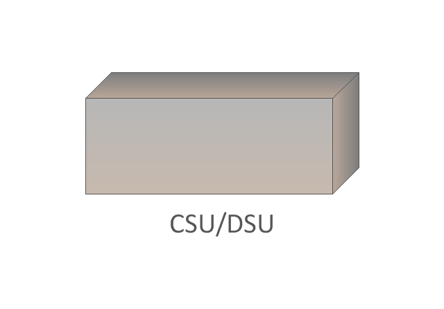
CSU/DSU

WAN

University

Government building

Home Office

Telecommuter House PC

Medium Building, Regular

Headquarters, Subdued

House, Regular

Small Business

Network Connector

Dynamic Connector

Line Connector

Line-curve Connector

Bus

FDDI Ring

Peer-to-peer

Token-ring

Star

Comm-link

Curved Bus

Ethernet

Cloud

Speaker

Microphone

Router

ATM Router

ISDN Switch

ATM Switch

ATM/FastGB Etherswitch

Workgroup Switch

Small Hub

100BaseT Hub

CDDI-FDDI

The vector stencils library "Computer network" contains 51 symbols of computer network devices and equipment for drawing computer network diagrams.
"Network Mapping Software.
A number of software tools exist to design computer network diagrams / or generate visual maps of networks, servers, storage, services, data centers, and other peripherals. Broadly, there are two types of software tools - those that help create diagrams manually and those that generate them using automated / semi-automated approaches.
Type of Software.
(1) Manual - allows users to design and draw logical and physical topology diagrams by manually placing icons and connections.
(2) Automated - generate topology diagrams / maps by traversing the network and automatically discovering resident devices or by importing network data." [Comparison of network diagram software. Wikipedia]
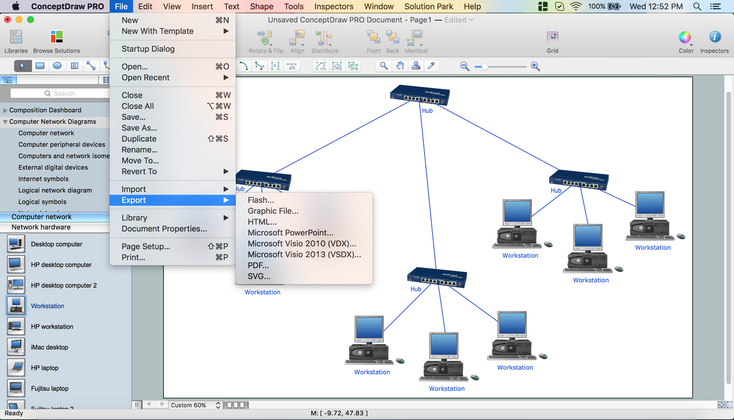
ConceptDraw PRO is the software for manual design of computer network diagrams. The solutions of the Computer and Networks area in ConceptDraw Solution Park extend ConceptDraw PRO with vector stencils libraries, templates and examples for creating the computer network diagrams.
The symbols example "Computer network - Vector stencils library" was created using the ConceptDraw PRO diagramming and vector drawing software extended with the Computer and Networks solution from the Computer and Networks area of ConceptDraw Solution Park.
www.conceptdraw.com/ solution-park/ computer-and-networks
"Network Mapping Software.
A number of software tools exist to design computer network diagrams / or generate visual maps of networks, servers, storage, services, data centers, and other peripherals. Broadly, there are two types of software tools - those that help create diagrams manually and those that generate them using automated / semi-automated approaches.
Type of Software.
(1) Manual - allows users to design and draw logical and physical topology diagrams by manually placing icons and connections.
(2) Automated - generate topology diagrams / maps by traversing the network and automatically discovering resident devices or by importing network data." [Comparison of network diagram software. Wikipedia]
ConceptDraw PRO is the software for manual design of computer network diagrams. The solutions of the Computer and Networks area in ConceptDraw Solution Park extend ConceptDraw PRO with vector stencils libraries, templates and examples for creating the computer network diagrams.
The symbols example "Computer network - Vector stencils library" was created using the ConceptDraw PRO diagramming and vector drawing software extended with the Computer and Networks solution from the Computer and Networks area of ConceptDraw Solution Park.
www.conceptdraw.com/ solution-park/ computer-and-networks
Laptop

Desktop computer

Firewall

Bus

Ethernet

Star network

FDDI Ring

Token-ring

Comm-link

Modem

Laser printer

Inkjet printer

Image scanner

City

Ethernet hub

Wireless router

Network switch

iPod Classic

iPhone/ iPod Touch

Xserve RAID

XServe

Apple Thunderbolt Display

Data store

Mac Pro

iMac

RAID

Mainframe

Rack-mountable server

Server

PDA

Cloud

Computer monitor

Workstation

Router

IP Phone

Fax

Mobile phone

Smartphone

Compact Disk

Mouse

Apple Wireless Mouse

Computer keyboard

Apple Keyboard

Radio tower

Satellite dish

Satellite

Webcam

AirPort Extreme

Airport Express

MacBook

iPhone 4

The vector stencils library "Cisco WAN" contains 15 symbols of wide area network (WAN) devices and equipment for drawing Cisco WAN diagrams.
"A wide area network (WAN) is a network that covers a broad area (i.e., any telecommunications network that links across metropolitan, regional, or national boundaries) using leased telecommunication lines. Business and government entities utilize WANs to relay data among employees, clients, buyers, and suppliers from various geographical locations. ...
Related terms for other types of networks are personal area networks (PANs), local area networks (LANs), campus area networks (CANs), or metropolitan area networks (MANs) which are usually limited to a room, building, campus or specific metropolitan area (e.g., a city) respectively.
... it may be best to view WANs as computer networking technologies used to transmit data over long distances, and between different LANs, MANs and other localised computer networking architectures. ...
WANs are often built using leased lines. At each end of the leased line, a router connects the LAN on one side with a second router within the LAN on the other. Leased lines can be very expensive. Instead of using leased lines, WANs can also be built using less costly circuit switching or packet switching methods. Network protocols including TCP/ IP deliver transport and addressing functions. Protocols including Packet over SONET/ SDH, MPLS, ATM and Frame relay are often used by service providers to deliver the links that are used in WANs." [Wide area network. Wikipedia]
The symbols example "Cisco WAN - Vector stencils library" was created using the ConceptDraw PRO diagramming and vector drawing software extended with the Cisco Network Diagrams solution from the Computer and Networks area of ConceptDraw Solution Park.
www.conceptdraw.com/ solution-park/ computer-networks-cisco
CSU/DSU
WAN
MUX
PBX switch
Hub
Hub, blue
NAT

Network cloud, dark
Network cloud, gold
Network cloud, white
Network cloud, standard color
Distributed director
Local director
PBX
DPT
- Cisco Switches and Hubs. Cisco icons , shapes, stencils and symbols
- Www Computer Network Hub
- Cisco Switches and Hubs. Cisco icons , shapes, stencils and ...
- Hub And Switch Cables Ppt
- Cisco Switches and Hubs. Cisco icons , shapes, stencils and ...
- Cisco Switches and Hubs. Cisco icons , shapes, stencils and symbols
- Star Network Topology | Cisco Switches and Hubs. Cisco icons ...
- Cisco Switches and Hubs. Cisco icons , shapes, stencils and ...
- Construction Diagram Of Computer Network Hub
- Network Hubs | Cisco Network Design. Cisco icons , shapes, stencils ...
- A Diagram Of Hub
- Network Hub Diagram
- Star Network Topology | Cisco Switches and Hubs. Cisco icons ...
- Cisco switches and hubs - Vector stencils library | Cisco switches ...
- 100baset Hub
- Cisco Switches and Hubs. Cisco icons , shapes, stencils and symbols
- Cisco Switches and Hubs. Cisco icons , shapes, stencils and symbols
- Computer Hub Diagrams
- How To Connect A Hub Switch And A Router
- Social determinants of health - Hub -and-spoke diagram | Network ...