"Sequence diagram is the most common kind of interaction diagram, which focuses on the message interchange between a number of lifelines.
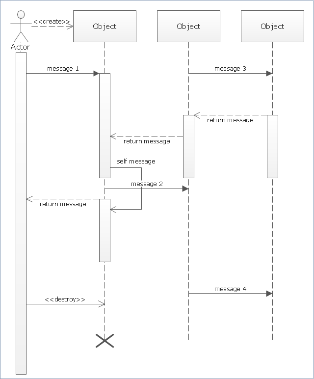
Sequence diagram describes an interaction by focusing on the sequence of messages that are exchanged, along with their corresponding occurrence specifications on the lifelines.
The following nodes and edges are typically drawn in a UML sequence diagram: lifeline, execution specification, message, combined fragment, interaction use, state invariant, continuation, destruction occurrence." [uml-diagrams.org/ sequence-diagrams.html]
The template "UML sequence diagram" for the ConceptDraw PRO diagramming and vector drawing software is included in the Rapid UML solution from the Software Development area of ConceptDraw Solution Park.
www.conceptdraw.com/ solution-park/ software-uml
UML sequence diagram
This example of automated teller machine (ATM) UML sequence diagram was created on the base of figure 5 "Sequence diagram" on the webpage "Message Sequence Charts and their Ilk" from the website of the University of California Irvine (UCI) Donald Bren School of Information and Computer Sciences.
"A UML sequence diagram or SD is similar to an MSC but written with a different notation. Presumably the same semantic issues arise, but possibly not since UML semantics are not well-defined. An example is shown in Figure 5.
The timelines are dotted rather than solid, and the name of the component is inside a box at the head of each timeline. The narrow rectangles apparently show when a component is active (unsure precisely what "active" means). An X on a timeline indicates that the component ceases to exist in some sense (unsure precisely how this is meant also). In the example, the Bank timeline has an X simply as an example (presumably the Bank does continue to exist)."
[www.ics.uci.edu/ ~alspaugh/ cls/ shr/ msc.html]
This example of bank ATM sequence diagram was created using the ConceptDraw PRO diagramming and vector drawing software extended with the ATM UML Diagrams solution from the Software Development area of ConceptDraw Solution Park.
Bank ATM UML sequence diagram

UML Sequence Diagram Example. SVG Vectored UML Diagrams Tools

Software Defined Networking System Overview


UML Software

UML Diagram Tool

UML Tool & UML Diagram Examples

UML Flowchart Symbols

Spatial infographics Design Elements: Transport Map

UML for Software Engineers

Basic Flowchart Symbols and Meaning


 Entity-Relationship Diagram (ERD)
Entity-Relationship Diagram (ERD) solution extends ConceptDraw PRO software with templates, samples and libraries of vector stencils from drawing the ER-diagrams by Chen's and crow’s foot notations.
UML State Machine Diagram.Design Elements

Technical Drawing Software

Maps and Directions

- UML sequence diagram - Template | Diagramming Software for ...
- UML package diagram - Template | UML Sequence Diagram | UML ...
- Uml Sequence Diagram Lifeline
- Difference Between Actor And Lifeline In Sequence Diagram
- What Is Sequence Diagram
- Design elements - Bank UML sequence diagram | Design elements ...
- UML communication diagram - Template | UML deployment diagram ...
- UML Sequence Diagram . Design Elements | ATM Sequence ...
- UML Sequence Diagram | Diagramming Software for designing ...
- UML Sequence Diagram . Design Elements | Design elements - UML ...
- Design elements - Bank UML sequence diagram
- Sequence Diagram Tool | Bank Sequence Diagram | Diagramming ...
- Data Flow Diagrams | ATM Sequence diagram | Basic Flowchart ...
- Timeline Diagrams | ATM Sequence diagram | Booch OOD Diagram ...
- Sequence Diagram Symbols
- Uml Sequence Diagram Symbols
- UML Sequence Diagram . Design Elements | Sequence Diagram ...
- Sequence Diagram Tool | Diagramming Software for designing UML ...
- Process Flowchart | Data Flow Diagrams | UML Sequence Diagram ...
- Diagramming Software for designing UML Sequence Diagrams ...