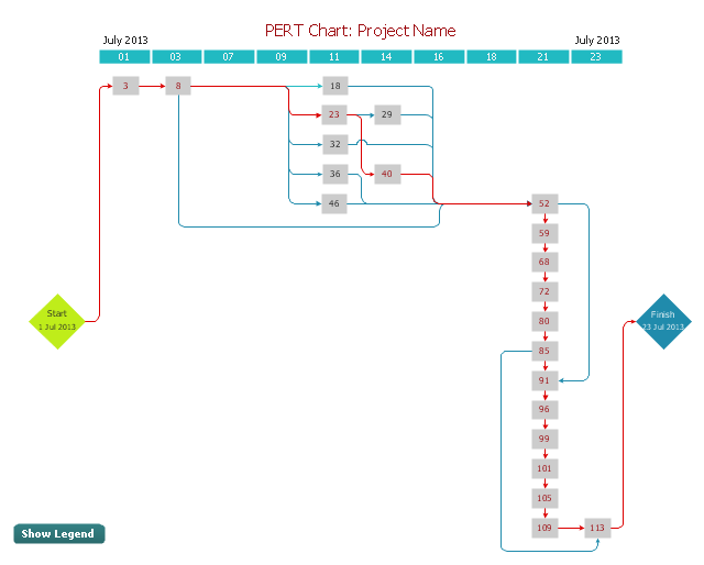
Activity Network (PERT) Chart

Activity on Node Network Diagramming Tool

HelpDesk
How To Create a PERT Chart Using PM Easy Solution

Activity Network Diagram Method

UML Class Diagram Example - Buildings and Rooms

Examples of Flowcharts, Org Charts and More


Affinity Diagram
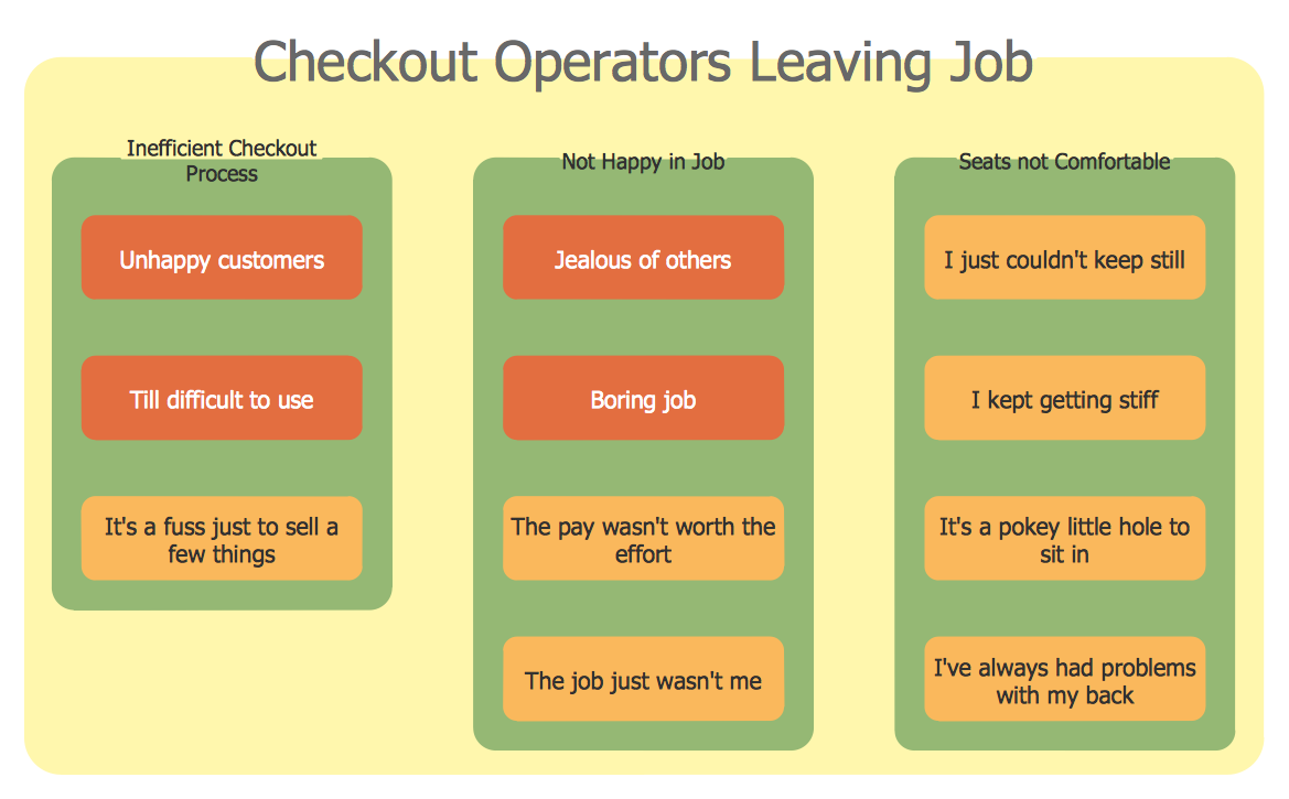
 Seven Management and Planning Tools
Seven Management and Planning Tools solution extends ConceptDraw DIAGRAM and ConceptDraw MINDMAP with features, templates, samples and libraries of vector stencils for drawing management mind maps and diagrams.
"A project network is a graph (flow chart) depicting the sequence in which a project's terminal elements are to be completed by showing terminal elements and their dependencies.
... the project network shows the "before-after" relations.
The most popular form of project network is activity on node, the other one is activity on arrow.
The condition for a valid project network is that it doesn't contain any circular references." [Project network. Wikipedia]
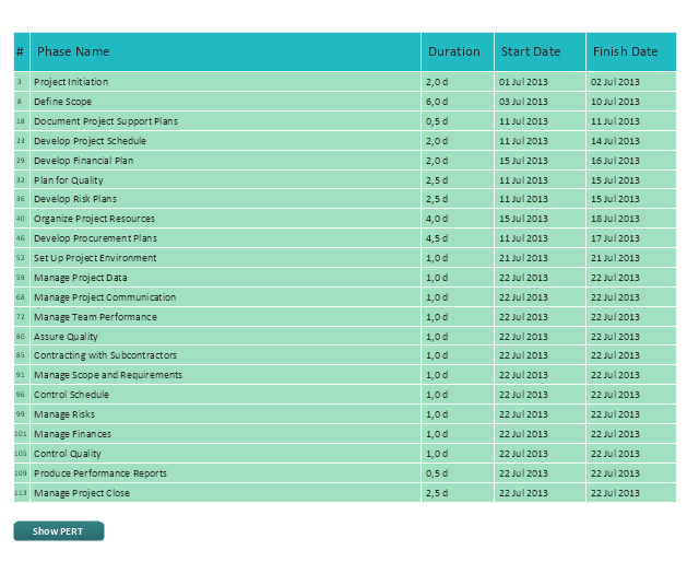
The PERT chart example "Project management plan" was created using the ConceptDraw PRO diagramming and vector drawing software extended with the solution "Seven Management and Planning Tools" from the Management area of ConceptDraw Solution Park.
... the project network shows the "before-after" relations.
The most popular form of project network is activity on node, the other one is activity on arrow.
The condition for a valid project network is that it doesn't contain any circular references." [Project network. Wikipedia]
The PERT chart example "Project management plan" was created using the ConceptDraw PRO diagramming and vector drawing software extended with the solution "Seven Management and Planning Tools" from the Management area of ConceptDraw Solution Park.
PERT
Legend
Swim Lane Diagrams

HelpDesk
How to Manage Problem Solving Using Seven Management and Planning Tools


UML Sample Project

HelpDesk
How to Create Project Diagrams on PC

- Activity on Node Network Diagramming Tool | PERT chart ...
- Program Evaluation and Review Technique ( PERT ) with ...
- Computer Network Diagrams | Cisco Network Templates | PERT ...
- ConceptDraw PRO Network Diagram Tool | Examples of Flowcharts ...
- Activity Network ( PERT ) Chart | How To Create a PERT Chart ...
- Examples of Flowcharts, Org Charts and More | Activity Network ...
- Activity Network ( PERT ) Chart | Examples of Flowcharts, Org Charts ...
- Activity Network ( PERT ) Chart | Process Flowchart | Flow chart ...
- ConceptDraw PRO Network Diagram Tool | Examples of Flowcharts ...
- Example Of Proposal
- ConceptDraw PRO Network Diagram Tool | Examples of Flowcharts ...
- Activity on Node Network Diagramming Tool | Activity Network ...
- Examples of Flowcharts, Org Charts and More | Activity Network ...
- Examples of Flowcharts, Org Charts and More | ConceptDraw PRO ...
- Pert Chart Project Examples
- Campus Area Networks (CAN). Computer and Network Examples ...
- PERT Chart Software | Activity Network ( PERT ) Chart | How To ...
- Activity Network ( PERT ) Chart | PERT chart - Template | How To ...
- Activity Network ( PERT ) Chart | Activity Network Diagram Method ...
- Process Flowchart | Activity on Node Network Diagramming Tool ...