Flowchart Components

UML Use Case Diagram Example - Estate Agency

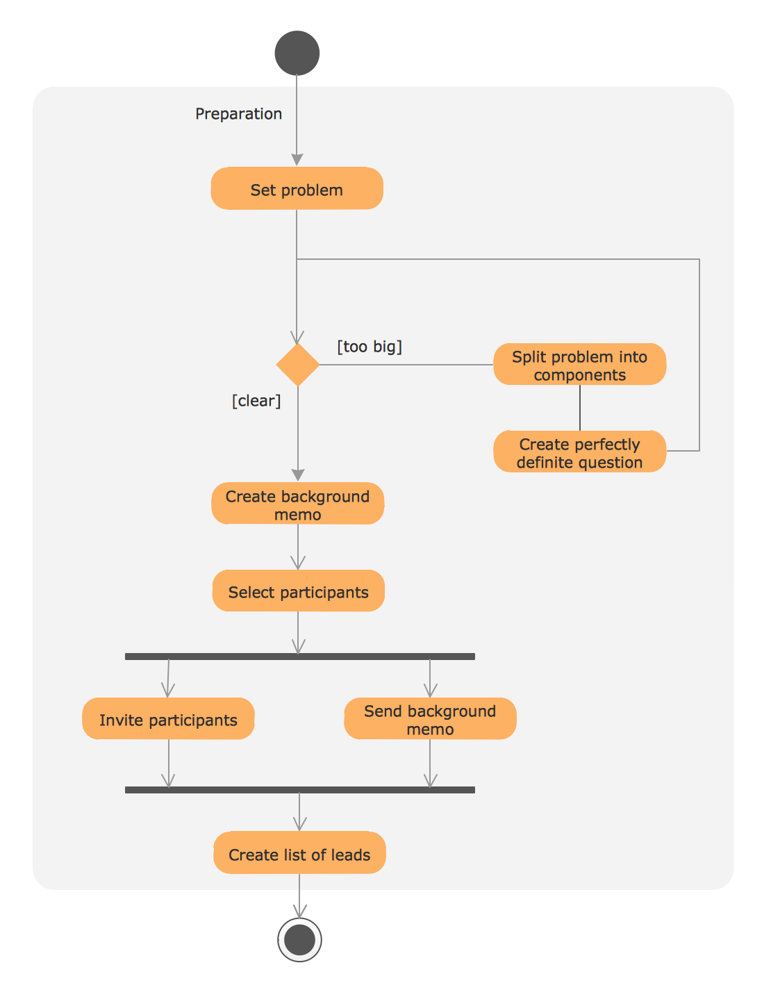
UML Process Diagram Example
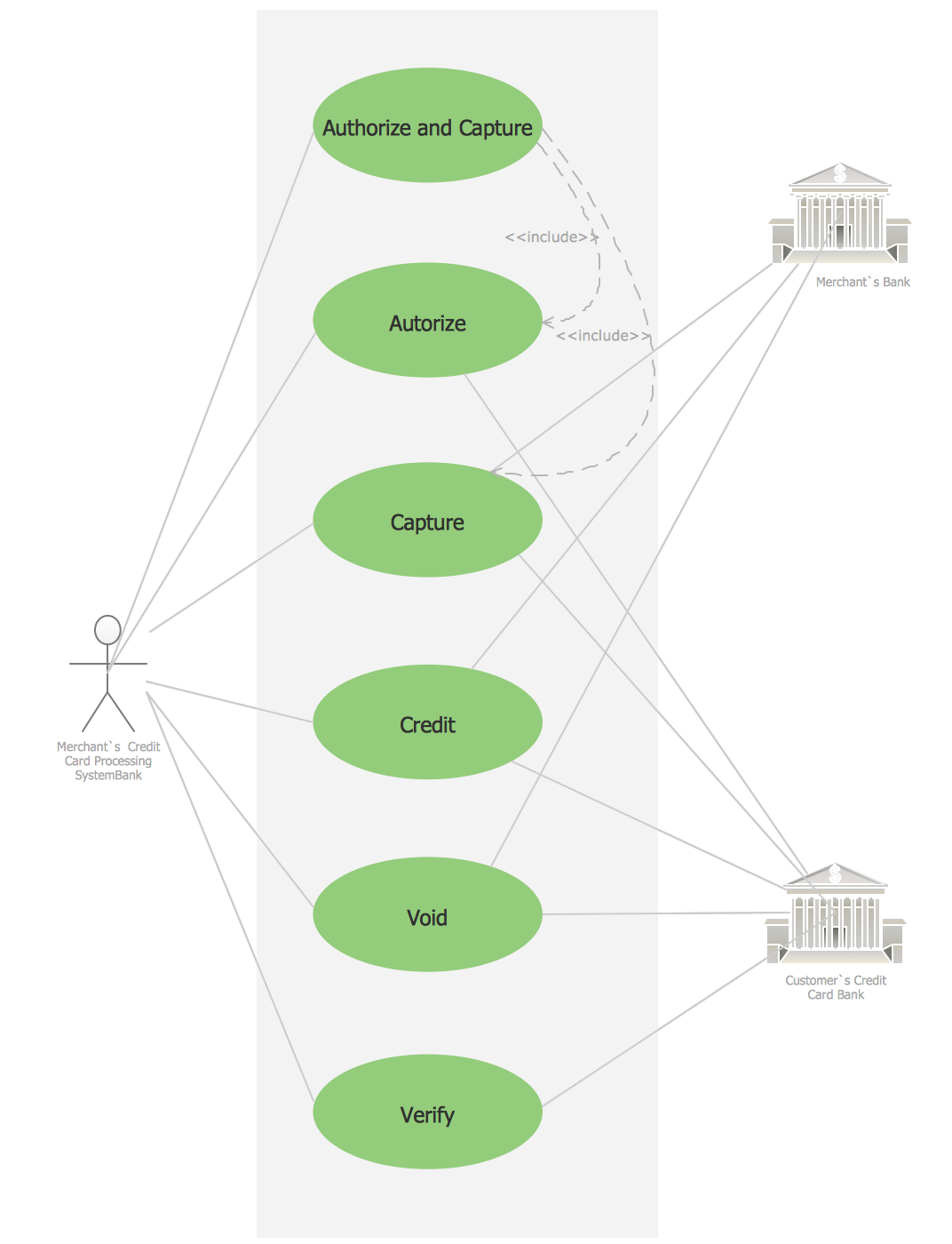
Credit Card Processing System UML Diagram
This example of UML class diagram models bank account system.
"A bank account is a financial account between a bank customer and a financial institution. A bank account can be a deposit account, a credit card, or any other type of account offered by a financial institution. The financial transactions which have occurred within a given period of time on a bank account are reported to the customer on a bank statement and the balance of the account at any point in time is the financial position of the customer with the institution. a fund that a customer has entrusted to a bank and from which the customer can make withdrawals." [Bank account. Wikipedia]
This bank account system UML class diagram example was created using the ConceptDraw PRO diagramming and vector drawing software extended with the ATM UML Diagrams solution from the Software Development area of ConceptDraw Solution Park.
UML class diagram of bank account system

ConceptDraw DIAGRAM ER Diagram Tool

Data Flow Diagram

Entity Relationship Diagram Symbols

Data structure diagram with ConceptDraw DIAGRAM

Swim Lane Diagrams

- State Machine Diagram | UML Use Case Diagram Example ...
- UML use case diagram - Banking system
- Diagramming Software for Design UML Use Case Diagrams | UML ...
- Bank ATM use case diagram | How to Create a Bank ATM Use Case ...
- How to Create a Bank ATM Use Case Diagram | ATM UML ...
- Class UML Diagram for Bank Account System | ATM UML Diagrams ...
- ATM Sequence diagram | UML activity diagram - Cash withdrawal ...
- UML Deployment Diagram Example - ATM System UML diagrams ...
- Bank Sequence Diagram | ATM UML Diagrams | Bank ATM use ...
- Process Flowchart | Technical Flow Chart Example | UML Tool ...