This mechanical room HVAC plan sample shows the layout of air handler (air handling unit, AHU) equipment: mixing chamber, air filter, fan (blower), heat exchanger coil, diffusers.
"Ventilating (the V in HVAC) is the process of "changing" or replacing air in any space to provide high indoor air quality (i.e. to control temperature, replenish oxygen, or remove moisture, odors, smoke, heat, dust, airborne bacteria, and carbon dioxide). Ventilation is used to remove unpleasant smells and excessive moisture, introduce outside air, to keep interior building air circulating, and to prevent stagnation of the interior air.
Ventilation includes both the exchange of air to the outside as well as circulation of air within the building. It is one of the most important factors for maintaining acceptable indoor air quality in buildings. Methods for ventilating a building may be divided into mechanical/ forced and natural types.
"Mechanical" or "forced" ventilation is used to control indoor air quality. Excess humidity, odors, and contaminants can often be controlled via dilution or replacement with outside air. However, in humid climates much energy is required to remove excess moisture from ventilation air.
Ventilation increases the energy needed for heating or cooling, however heat recovery ventilation can be used to mitigate the energy consumption. This involves heat exchange between incoming and outgoing air. Energy recovery ventilation additionally includes exchange of humidity." [Ventilation (architecture). Wikipedia]
The HVAC floor plan example "Ventilation system layout" was created using the ConceptDraw PRO diagramming and vector drawing software extended with the HVAC Plans solution from the Building Plans area of ConceptDraw Solution Park.
HVAC floor plan
 Plumbing and Piping Plans
Plumbing and Piping Plans solution extends ConceptDraw PRO v10.2.2 software with samples, templates and libraries of pipes, plumbing, and valves design elements for developing of water and plumbing systems, and for drawing Plumbing plan, Piping plan, PVC Pipe plan, PVC Pipe furniture plan, Plumbing layout plan, Plumbing floor plan, Half pipe plans, Pipe bender plans.
This HVAC floor plan sample shows the ventilation duct system layout.
"Ducts are used in heating, ventilation, and air conditioning (HVAC) to deliver and remove air. The needed airflows include, for example, supply air, return air, and exhaust air. Ducts commonly also deliver ventilation air as part of the supply air. As such, air ducts are one method of ensuring acceptable indoor air quality as well as thermal comfort.
A duct system is also called ductwork. Planning (laying out), sizing, optimizing, detailing, and finding the pressure losses through a duct system is called duct design." [Duct (flow). Wikipedia]
The HVAC floor plan example "Ductwork layout" was created using the ConceptDraw PRO diagramming and vector drawing software extended with the HVAC Plans solution from the Building Plans area of ConceptDraw Solution Park.
HVAC floor plan

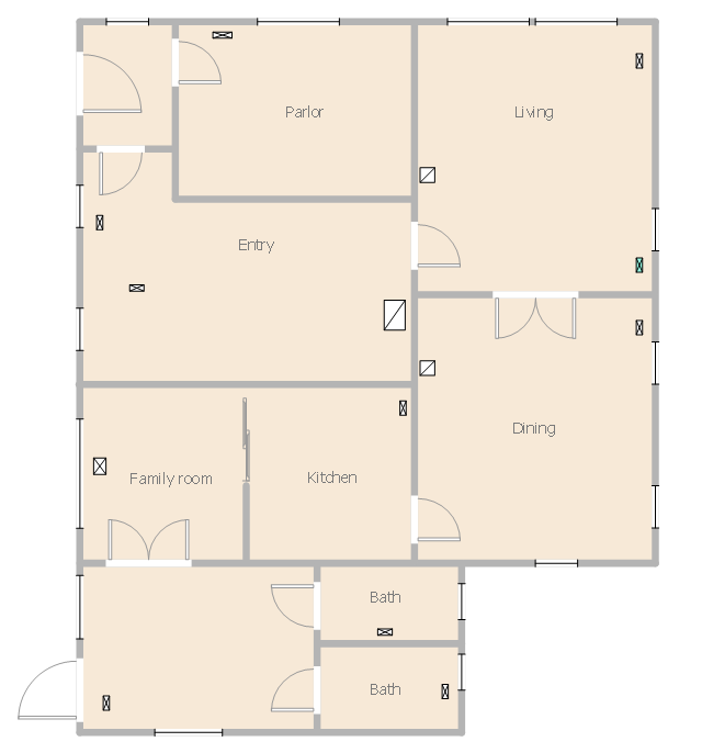
This house HVAC floor plan sample shows the ventilation system air supply diffusers and air exhaust grilles layout.
""The intentional introduction of outside air can be categorized as either mechanical ventilation, or natural ventilation. Mechanical ventilation uses fans to drive the flow of outside air into a building. This may be accomplished by pressurization (in the case of positively pressurized buildings), or by depressurization (in the case of exhaust ventilation systems). Many mechanically ventilated buildings use a combination of both, with the ventilation being integrated into the HVAC system. Natural ventilation is the intentional passive flow of outside air into a building through planned openings (such as louvers, doors, and windows). Natural ventilation does not require mechanical systems to move outside air, it relies entirely on passive physical phenomena, such as wind pressure, or the stack effect. Mixed mode ventilation systems use both mechanical and natural processes." [Ventilation (architecture). Wikipedia]
The HVAC floor plan example "House ventilation" was created using the ConceptDraw PRO diagramming and vector drawing software extended with the HVAC Plans solution from the Building Plans area of ConceptDraw Solution Park.
HVAC floor plan
How To use House Electrical Plan Software


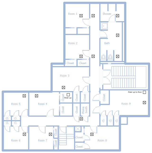
This school HVAC plan sample represent layout of air conditioning ductwork inlets and outlets.
"Air conditioning (often referred to as A/ C or AC) is the process of altering the properties of air (primarily temperature and humidity) to more comfortable conditions, typically with the aim of distributing the conditioned air to an occupied space such as a building or a vehicle to improve thermal comfort and indoor air quality. In common use, an air conditioner is a device that removes heat from the air inside a building or vehicle, thus lowering the air temperature. The cooling is typically achieved through a refrigeration cycle, but sometimes evaporation or free cooling is used. Air conditioning systems can also be made based on desiccants." [Air conditioning. Wikipedia]
The fllor plan example "School HVAC plan" was created using the ConceptDraw PRO diagramming and vector drawing software extended with the HVAC Plans solution from the Building Plans area of ConceptDraw Solution Park.
Floor plan
 HVAC Plans
Use HVAC Plans solution to create professional, clear and vivid HVAC-systems design plans, which represent effectively your HVAC marketing plan ideas, develop plans for modern ventilation units, central air heaters, to display the refrigeration systems for automated buildings control, environmental control, and energy systems.
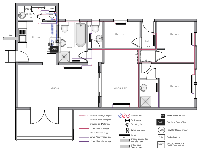
This plumbing and piping plan sample illustrates the house water heating system.
"Water heating is a thermodynamic process that uses an energy source to heat water above its initial temperature. Typical domestic uses of hot water include cooking, cleaning, bathing, and space heating. ...
Domestically, water is traditionally heated in vessels known as water heaters, kettles, cauldrons, pots, or coppers. These metal vessels that heat a batch of water do not produce a continual supply of heated water at a preset temperature. ...
Appliances that provide a continual supply of hot water are called water heaters, hot water heaters, hot water tanks, boilers, heat exchangers, geysers, or calorifiers. ... In domestic installations, potable water heated for uses other than space heating is also called domestic hot water (DHW)." [Water heating. Wikipedia]
The plumbing and piping plan example "House water heating" was created using the ConceptDraw PRO diagramming and vector drawing software extended with the Plumbing and Piping Plans solution from the Building Plans area of ConceptDraw Solution Park.
Plumbing and piping plan
Building Drawing Software for Design Registers, Drills and Diffusers


HelpDesk
How to Create a HVAC Plan

 Reflected Ceiling Plans
Reflected Ceiling Plans solution is effective tool for architects, designers, electricians, and other people which every day need convenient tool for representing their ceiling ideas. Use it to create without efforts professional Reflected Ceiling plans and Reflective Ceiling plans, showing the location of light fixtures, drywall or t-bar ceiling patterns, lighting panels, and HVAC grilles and diffusers that may be suspended from the ceiling.
Electrical Symbols — VHF UHF SHF

- HVAC Plans
- Air handler- HVAC plan | Design elements - Windows and doors ...
- Representation Of Duct On A Floor Plan
- HVAC Plans | RCP - HVAC layout | How to Create a HVAC Plan ...
- How to Create a HVAC Plan | Ventilation system layout | Ventilation ...
- Apartment HVAC plan | Plumbing and Piping Plans | Toilet Duct In ...
- Ductwork layout | HVAC Plans | Design elements - HVAC ductwork ...
- Duct On Floor Plans
- Design elements - Doors and windows | Create Floor Plans Easily ...
- Design elements - HVAC ductwork | HVAC Plans | Ventilation ...
- Air handler- HVAC plan | Ventilation system layout | Hvac Ahu To ...
- Ductwork layout | Apartment HVAC plan | School HVAC plan | Toilet ...
- Ventilation system layout | HVAC Plans | How to Create a HVAC ...
- Ventilation system layout | Create Floor Plans Easily with ...
- Ventilation system layout | Ductwork layout | Building Plans Area ...
- Ductwork layout | House tap water supply | Plumbing and Piping ...
- Design elements - HVAC ductwork | Air handler- HVAC plan ...
- Ventilation Floor Plan
- Air handler- HVAC plan | Planning Of Ahu With Duct Work
- Ductwork layout | Interior Design Registers, Drills and Diffusers ...