This site uses cookies. By continuing to browse the ConceptDraw site you are agreeing to our Use of Site Cookies.

Fully Connected Network Topology Diagram

The Fully Connected Network Topology Diagram examples was created using ConceptDraw DIAGRAM software with Computer and Networks solution.
The Computer and Networks solution from Computer and Networks area of ConceptDraw Solution Park provides examples, templates and vector stencils library with symbols of local area network (LAN) and wireless LAN (WLAN) equipment.

Tree Network Topology Diagram

The Tree Network Topology Diagram examples was created using ConceptDraw DIAGRAM software with Computer and Networks solution.

Complete Network Topology

This sample was created in ConceptDraw DIAGRAM diagramming and vector drawing software using the Computer and Networks solution from Computer and Networks area of ConceptDraw Solution Park.
A complete (fully connected) topology is a network topology in which there is a direct link between all pairs of nodes. In a fully connected network with n nodes, there are n(n-1)/2 direct links. Networks designed with this topology are usually very expensive to set up, but provide a high degree of reliability due to the multiple paths for data that are provided by the large number of redundant links between nodes.

Network Topologies

ConceptDraw DIAGRAM is a powerful Network Topology Diagram software thanks to the Computer Network Diagrams Solution from the Computer and Networks Area. It's very easy and quickly to design the network topologies diagrams of any kinds and complexity in ConceptDraw DIAGRAM diagramming and vector drawing software.

Easy to draw network topology, physical network, logical network, network mapping, home area networks (HAN), wireless network, cisco network topologies, fully connected network topology, bus network topology, star network topology, ring network topology, mesh network topology, tree network topology.
Create Network Topology Diagram

Daisy Chain Network Topology

This sample was created in ConceptDraw DIAGRAM diagramming and vector drawing software using the Computer and Networks solution from Computer and Networks area of ConceptDraw Solution Park.
A Daisy Chain is the simple computer network. It is the easiest way to add more Ethernet devices into the network. In the Daisy Chain network one computer is connected to the next without any intervening devices, thus the message is sent from one computer to the next and then to the next and so on. A Daisy Chain can be linear or ring

Network Topologies

ConceptDraw DIAGRAM is a powerful Network Topology Diagram software thanks to the Computer Network Diagrams Solution from the Computer and Networks Area. It's very easy and quickly to design the network topologies diagrams of any kinds and complexity in ConceptDraw DIAGRAM diagramming and vector drawing software.

Easy to draw network topology, physical network, logical network, network mapping, home area networks (HAN), wireless network, cisco network topologies, fully connected network topology, bus network topology, star network topology, ring network topology, mesh network topology, tree network topology.
Create Network Topology Diagram

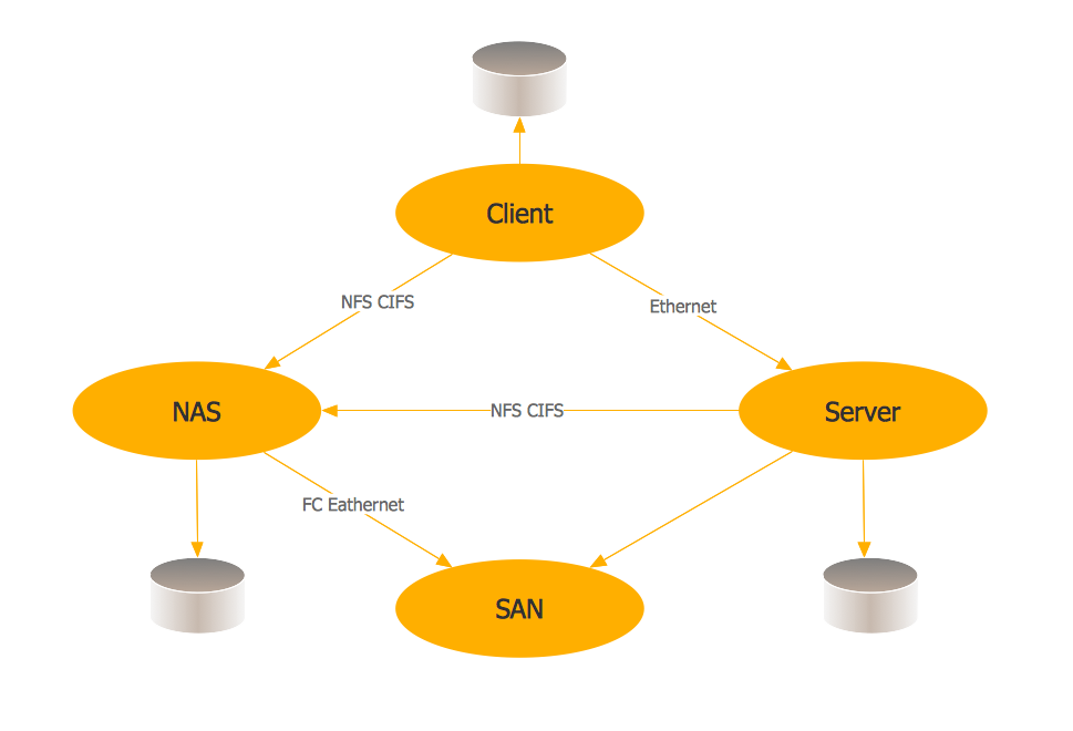
Storage area networks (SAN). Computer and Network Examples

A Storage area network (SAN) is a dedicated network that provides access to data storage and operations only on the block level. SAN usually has own network of storage devices/elements and disk arrays that are connected with each other and to a remote data-sharing network. SANs are widely used for enhancing the storage devices (optical jukeboxes, disk arrays, tape libraries) that are accessible for networked servers.
This example was created in ConceptDraw DIAGRAM using the Computer and Networks Area of ConceptDraw Solution Park. It shows the hybrid of Storage area network (SAN) and Network Attached Storage (NAS) technologies.

Network Topology Mapper

Network Topology in communication networks, a topology is a usually schematic description of the arrangement of a network, including its nodes and connecting lines. There are two ways of defining network geometry: the physical topology and the logical topology.

Network Topology Mapper offers extensive drawing tools professional-looking network diagrams quickly and easily allowing you to clearly represent and communicate network architecture, topology, and design to engineers, stakeholders and end-users.

Network diagrams with ConceptDraw DIAGRAM

Network diagram is the tool for description, study and analysis of network knots and connections between these knots. Created network diagram can present you the existing information in comprehensible graphic view.
Network diagrams are divided into Physical Network Diagrams and Logical Network Diagrams.
Network diagram is an indispensable tool for network administrators and engineers at development of new networks and management of existing networks.

ERD Symbols and Meanings

Crow's foot notation is used in Barker's Notation, Structured Systems Analysis and Design Method (SSADM) and information engineering. Crow's foot diagrams represent entities as boxes, and relationships as lines between the boxes. Different shapes at the ends of these lines represent the cardinality of the relationship.
The Chen's ERD notation is still used and is considered to present a more detailed way of representing entities and relationships.
To create an ERD, software engineers mainly turn to dedicated drawing software, which contain the full notation resources for their specific database design - ERD symbols and meanings. CS Odessa has released an all-inclusive Entity-Relationship Diagram (ERD) solution for their powerful drawing program, ConceptDraw DIAGRAM.
How to Build an Entity Relationship Diagram (ERD)