Network Topologies


Network Glossary Definition


How to Build Cloud Computing Diagram Principal Cloud Manufacturing

The vector stencils library "Computer network" contains 51 symbols of computer network devices and equipment for drawing computer network diagrams.
"Network Mapping Software.
A number of software tools exist to design computer network diagrams / or generate visual maps of networks, servers, storage, services, data centers, and other peripherals. Broadly, there are two types of software tools - those that help create diagrams manually and those that generate them using automated / semi-automated approaches.
Type of Software.
(1) Manual - allows users to design and draw logical and physical topology diagrams by manually placing icons and connections.
(2) Automated - generate topology diagrams / maps by traversing the network and automatically discovering resident devices or by importing network data." [Comparison of network diagram software. Wikipedia]
ConceptDraw PRO is the software for manual design of computer network diagrams. The solutions of the Computer and Networks area in ConceptDraw Solution Park extend ConceptDraw PRO with vector stencils libraries, templates and examples for creating the computer network diagrams.
The symbols example "Computer network - Vector stencils library" was created using the ConceptDraw PRO diagramming and vector drawing software extended with the Computer and Networks solution from the Computer and Networks area of ConceptDraw Solution Park.
www.conceptdraw.com/ solution-park/ computer-and-networks
Laptop

Desktop computer

Firewall

Bus

Ethernet

Star network

FDDI Ring

Token-ring

Comm-link

Modem

Laser printer

Inkjet printer

Image scanner

City

Ethernet hub

Wireless router

Network switch

iPod Classic

iPhone/ iPod Touch

Xserve RAID

XServe

Apple Thunderbolt Display

Data store

Mac Pro

iMac

RAID

Mainframe

Rack-mountable server

Server

PDA

Cloud

Computer monitor

Workstation

Router

IP Phone

Fax

Mobile phone

Smartphone

Compact Disk

Mouse

Apple Wireless Mouse

Computer keyboard

Apple Keyboard

Radio tower

Satellite dish

Satellite

Webcam

AirPort Extreme

Airport Express

MacBook

iPhone 4

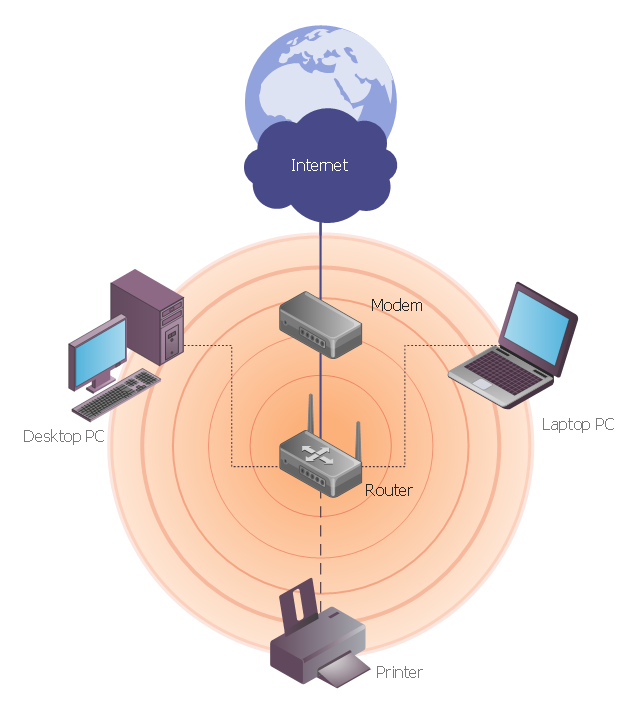
This network diagram sample depicts usage of wireless access point.
"In computer networking, a wireless access point (AP) is a device that allows wireless devices to connect to a wired network using Wi-Fi, or related standards. The AP usually connects to a router (via a wired network) as a standalone device, but it can also be an integral component of the router itself. ...
With the creation of the wireless Access Point (AP), network users are now able to add devices that access the network with few or no cables. An AP normally connects directly to a wired Ethernet connection and the AP then provides wireless connections using radio frequency links for other devices to utilize that wired connection. Most APs support the connection of multiple wireless devices to one wired connection. Modern APs are built to support a standard for sending and receiving data using, these radio frequencies. Those standards, and the frequencies they use are defined by the IEEE. Most APs use IEEE 802.11 standards." [Wireless access point. Wikipedia]
The wireless network diagram example "Wireless access point" was created using the ConceptDraw PRO diagramming and vector drawing software extended with the Wireless Networks solution from the Computer and Networks area of ConceptDraw Solution Park.
Wireless network diagram
Interior Design. Office Layout Plan Design Element


The vector stencils library "Active Directory" contains 20 symbols of Active Directory elements for drawing AD network diagrams. It helps network and system administrators to visualize Microsoft Windows Active Directory structures for network design, installation and maintainance.
"An Active Directory structure is an arrangement of information about objects. The objects fall into two broad categories: resources (e.g., printers) and security principals (user or computer accounts and groups). Security principals are assigned unique security identifiers (SIDs).
Each object represents a single entity - whether a user, a computer, a printer, or a group - and its attributes. Certain objects can contain other objects. An object is uniquely identified by its name and has a set of attributes - the characteristics and information that the object represents - defined by a schema, which also determines the kinds of objects that can be stored in Active Directory.
The schema object lets administrators extend or modify the schema when necessary. However, because each schema object is integral to the definition of Active Directory objects, deactivating or changing these objects can fundamentally change or disrupt a deployment. Schema changes automatically propagate throughout the system. Once created, an object can only be deactivated - not deleted. Changing the schema usually requires planning. Sites are implemented as a set of well-connected subnets." [Active Directory. Wikipedia]
The AD symbols example "Active Directory - Vector stencils library" was created using the ConceptDraw PRO diagramming and vector drawing software extended with the Active Directory Diagrams solution from the Computer and Networks area of ConceptDraw Solution Park.
www.conceptdraw.com/ solution-park/ active-directory-diagrams
Domain
Computer
User

Group

Container

Print queue
Contact

Organizational unit
Policy
Volume
Generic object

Site
Site link
Site link bridge
Server

NTDS site settings
IP subnet
Certificate template

Licensing site

Connection
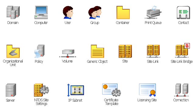
The vector stencils library "Active Directory" contains 20 symbols of Active Directory objects for drawing AD network diagrams. It helps network and system administrators to visualize Microsoft Windows Active Directory structures for network design, installation and maintainance.
"Objects.
An Active Directory structure is an arrangement of information about objects. The objects fall into two broad categories: resources (e.g., printers) and security principals (user or computer accounts and groups). Security principals are assigned unique security identifiers (SIDs).
Each object represents a single entity - whether a user, a computer, a printer, or a group - and its attributes. Certain objects can contain other objects. An object is uniquely identified by its name and has a set of attributes - the characteristics and information that the object represents - defined by a schema, which also determines the kinds of objects that can be stored in Active Directory.
The schema object lets administrators extend or modify the schema when necessary. However, because each schema object is integral to the definition of Active Directory objects, deactivating or changing these objects can fundamentally change or disrupt a deployment. Schema changes automatically propagate throughout the system. Once created, an object can only be deactivated - not deleted. Changing the schema usually requires planning. Sites are implemented as a set of well-connected subnets." [Active Directory. Wikipedia]
The shapes example "Design elements - Active Directory" was created using the ConceptDraw PRO diagramming and vector drawing software extended with the Active Directory Diagrams solution from the Computer and Networks area of ConceptDraw Solution Park.
Active Directory symbols
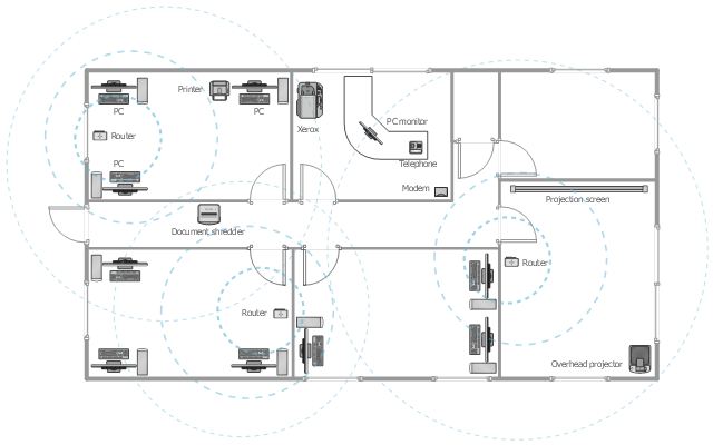
This office floor plan sample depicts the equipment layout of wireless computer network.
"A wireless local area network (WLAN) links two or more devices using some wireless distribution method (typically spread-spectrum or OFDM radio), and usually providing a connection through an access point to the wider Internet. This gives users the ability to move around within a local coverage area and still be connected to the network. Most modern WLANs are based on IEEE 802.11 standards, marketed under the Wi-Fi brand name." [Wireless LAN. Wikipedia]
The equipment layout example "Office wireless network plan" was created using the ConceptDraw DIAGRAM diagramming and vector drawing software extended with the Office Layout Plans solution from the Building Plans area of ConceptDraw Solution Park.
Equipment layout
"The Ethernet physical layer is the physical layer component of the Ethernet family of computer network standards.
The Ethernet physical layer evolved over a considerable time span and encompasses quite a few physical media interfaces and several magnitudes of speed. The speed ranges from 1 Mbit/ s to 100 Gbit/ s, while the physical medium can range from bulky coaxial cable to twisted pair and optical fiber. In general, network protocol stack software will work similarly on all physical layers.
10-gigabit Ethernet was already used in both enterprise and carrier networks by 2007, with 40 Gbit/ s and 100 Gbit/ s Ethernet ratified. ...
Many Ethernet adapters and switch ports support multiple speeds, using autonegotiation to set the speed and duplex for the best values supported by both connected devices. If auto-negotiation fails, a multiple-speed device will sense the speed used by its partner, but will assume half-duplex. A 10/ 100 Ethernet port supports 10BASE-T and 100BASE-TX. A 10/ 100/ 1000 Ethernet port supports 10BASE-T, 100BASE-TX, and 1000BASE-T." [Ethernet physical layer. Wikipedia]
The LAN equipment and cabling layout floorplan example "Ethernet local area network layout floor plan" was created using the ConceptDraw PRO diagramming and vector drawing software extended with the Network Layout Floor Plans solution from the Computer and Networks area of ConceptDraw Solution Park.
Ethernet LAN layout floorplan

- Diagram Physical Topologies | Logical network topology diagram ...
- Network Topologies | Tree Network Topology Diagram | Fully ...
- Network Printer | Physical LAN topology diagram | Using Both Wired ...
- How To use Switches in Network Diagram | Star Network Topology ...
- Network Printer | Network diagrams with ConceptDraw PRO ...
- Point to Point Network Topology
- Network Topologies | Star Network Topology | Hotel Network ...
- Hotel Network Topology Diagram | Local area network (LAN ...
- Wired Connection Diagram
- Network Topologies | Network topologies diagram | Network ...
- Hybrid Network Topology | Star Network Topology | Fully Connected ...
- Star Network Topology | How To use Switches in Network Diagram ...
- Network Printer | Computer network diagram - Template | Hotel ...
- Network Topologies | Hotel Network Topology Diagram | Hybrid ...
- Star Network Topology | Network Topologies | 10Base-T star ...
- Network Gateway Router | Hotel Network Topology Diagram | How ...
- Tree Network Topology Diagram | Fully Connected Network ...
- Logical network topology diagram | Local area network (LAN ...
- Network Topologies | Hotel Network Topology Diagram | Hybrid ...
- Diagram Physical Topologies | Network Topologies | Star Network ...