 Block Diagrams
Block diagrams solution extends ConceptDraw DIAGRAM software with templates, samples and libraries of vector stencils for drawing the block diagrams.
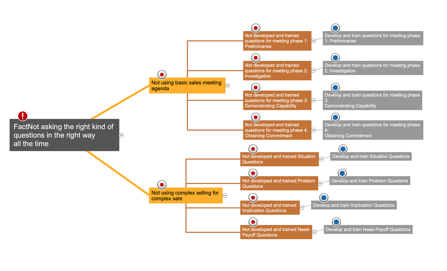
Cause and Effect Analysis

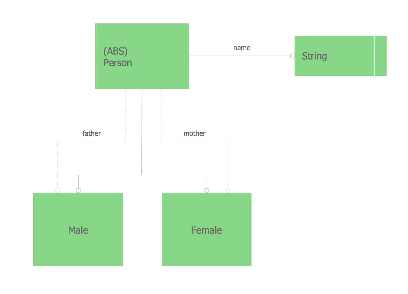
Express-G Diagram
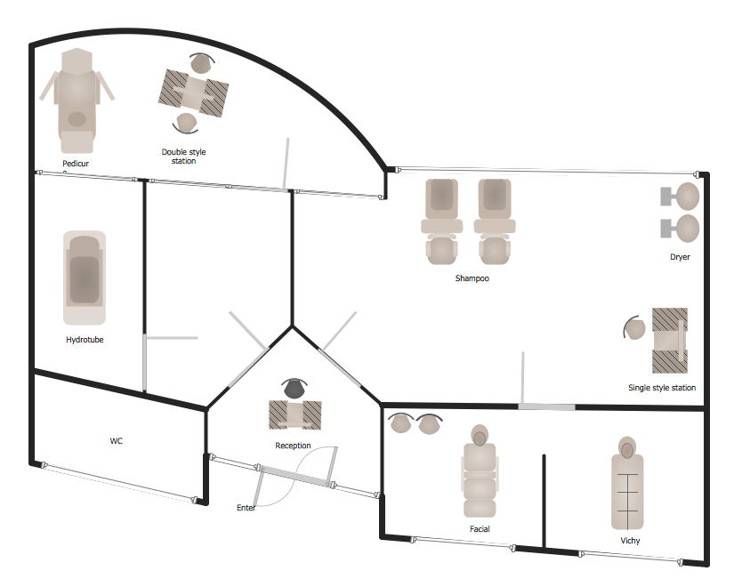
Spa Floor Plan
 Network Layout Floor Plans
Network Layout Floor Plans solution extends ConceptDraw DIAGRAM software functionality with powerful tools for quick and efficient documentation the network equipment and displaying its location on the professionally designed Network Layout Floor Plans. Never before creation of Network Layout Floor Plans, Network Communication Plans, Network Topologies Plans and Network Topology Maps was not so easy, convenient and fast as with predesigned templates, samples, examples and comprehensive set of vector design elements included to the Network Layout Floor Plans solution. All listed types of plans will be a good support for the future correct cabling and installation of network equipment.
Tools to Create Your Own Infographics

Electrical Symbols, Electrical Diagram Symbols

Sales Process Flowchart. Flowchart Examples

Electrical Symbols — Terminals and Connectors

Building Plan Software. Building Plan Examples

- Create A Family Tree
- Family Tree Entity Relationship Diagram
- PROBLEM ANALYSIS. Root Cause Analysis Tree Diagram | Family ...
- Family Relationship In A Flow Chart
- Family Emergency Plan | Express-G Diagram | ER Diagram ...
- Basic Flowchart Symbols and Meaning | Sample Tree Diagram For ...
- Family Relationships Diagram
- ConceptDraw Solution Park | Process Flowchart | Fault Tree ...
- Influence Diagram | Influence Diagram Software | Fault Tree ...
- Emergency Plan | How to Draw an Emergency Plan for Your Office ...