This cloud computing diagram example was drawn on the base of Wikimedia Commons file: Principal cloud manufacturing.png. [commons.wikimedia.org/ wiki/ File:Principal_ cloud_ manufacturing.png]
This file is licensed under the Creative Commons Attribution-Share Alike 3.0 Unported license. [creativecommons.org/ licenses/ by-sa/ 3.0/ deed.en]
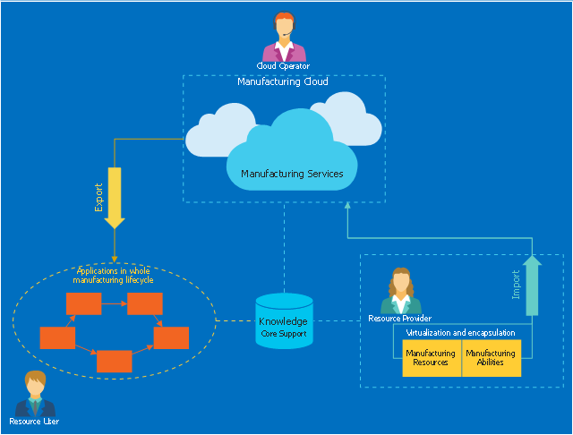
"Cloud manufacturing (CMfg) is a new manufacturing paradigm developed from existing advanced manufacturing models (e.g., ASP, AM, NM, MGrid) and enterprise information technologies under the support of cloud computing, Internet of Things (IoT), virtualization and service-oriented technologies, and advanced computing technologies. It transforms manufacturing resources and manufacturing capabilities into manufacturing services, which can be managed and operated in an intelligent and unified way to enable the full sharing and circulating of manufacturing resources and manufacturing capabilities. CMfg can provide safe and reliable, high quality, cheap and on-demand manufacturing services for the whole lifecycle of manufacturing." [Cloud manufacturing. Wikipedia]
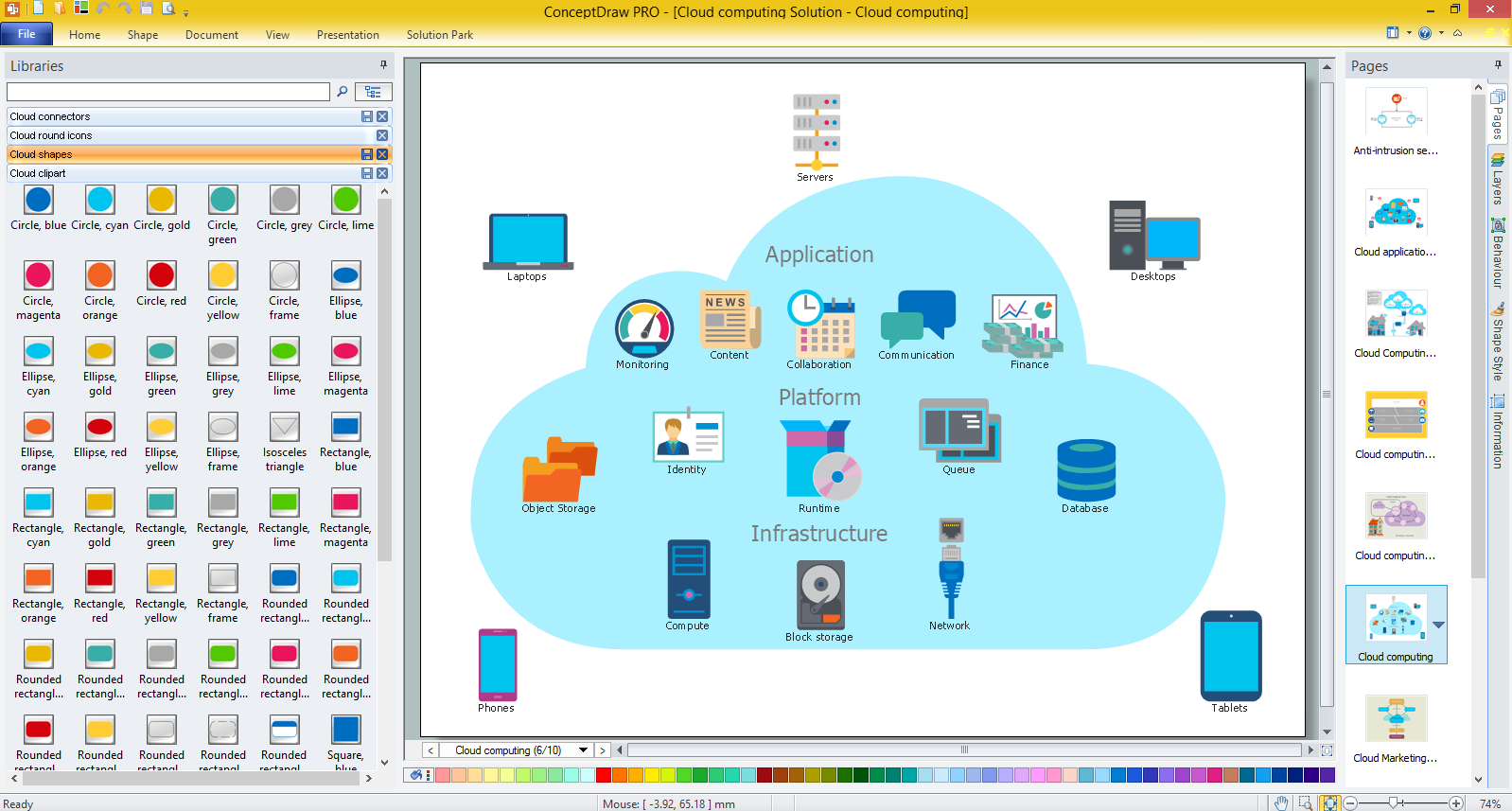
The cloud computing diagram example "Principal cloud manufacturing" was drawn using ConceptDraw PRO software extended with the Cloud Computing Diagrams solution from the Computer and Networks area of ConceptDraw Solution Park.
This file is licensed under the Creative Commons Attribution-Share Alike 3.0 Unported license. [creativecommons.org/ licenses/ by-sa/ 3.0/ deed.en]
"Cloud manufacturing (CMfg) is a new manufacturing paradigm developed from existing advanced manufacturing models (e.g., ASP, AM, NM, MGrid) and enterprise information technologies under the support of cloud computing, Internet of Things (IoT), virtualization and service-oriented technologies, and advanced computing technologies. It transforms manufacturing resources and manufacturing capabilities into manufacturing services, which can be managed and operated in an intelligent and unified way to enable the full sharing and circulating of manufacturing resources and manufacturing capabilities. CMfg can provide safe and reliable, high quality, cheap and on-demand manufacturing services for the whole lifecycle of manufacturing." [Cloud manufacturing. Wikipedia]
The cloud computing diagram example "Principal cloud manufacturing" was drawn using ConceptDraw PRO software extended with the Cloud Computing Diagrams solution from the Computer and Networks area of ConceptDraw Solution Park.
Cloud computing diagram example
This cloud computing diagram example was drawn on the base of Wikimedia Commons file: ArchitectureptSonde.png.
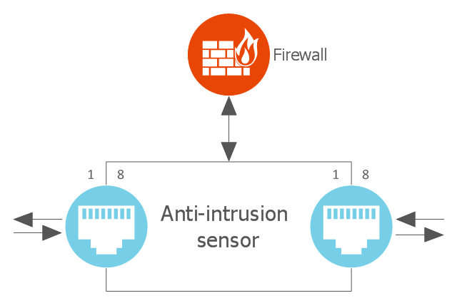
"Figure representing the architecture of an anti-intrusion sensor for cloud computing." [commons.wikimedia.org/ wiki/ File:ArchitectureptSonde.png]
This file is made available under the Creative Commons CC0 1.0 Universal Public Domain Dedication. [creativecommons.org/ publicdomain/ zero/ 1.0/ deed.en]
"A wireless sensor network (WSN) (sometimes called a wireless sensor and actuator network (WSAN)) are spatially distributed autonomous sensors to monitor physical or environmental conditions, such as temperature, sound, pressure, etc. and to cooperatively pass their data through the network to a main location. The more modern networks are bi-directional, also enabling control of sensor activity. The development of wireless sensor networks was motivated by military applications such as battlefield surveillance; today such networks are used in many industrial and consumer applications, such as industrial process monitoring and control, machine health monitoring, and so on." [Wireless sensor network. Wikipedia]
The cloud computing diagram example "Anti-intrusion sensor architecture" was drawn using ConceptDraw PRO software extended with the Cloud Computing Diagrams solution from the Computer and Networks area of ConceptDraw Solution Park.
Cloud computing diagram
How to Build Cloud Computing Diagram Principal Cloud Manufacturing

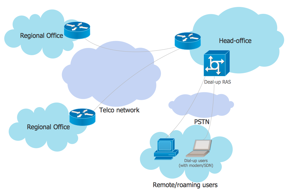
This Cisco network diagram example was redesigned from the Wikimedia Commons file: Frame relay.jpg. [commons.wikimedia.org/ wiki/ File:Frame_ relay.jpg]
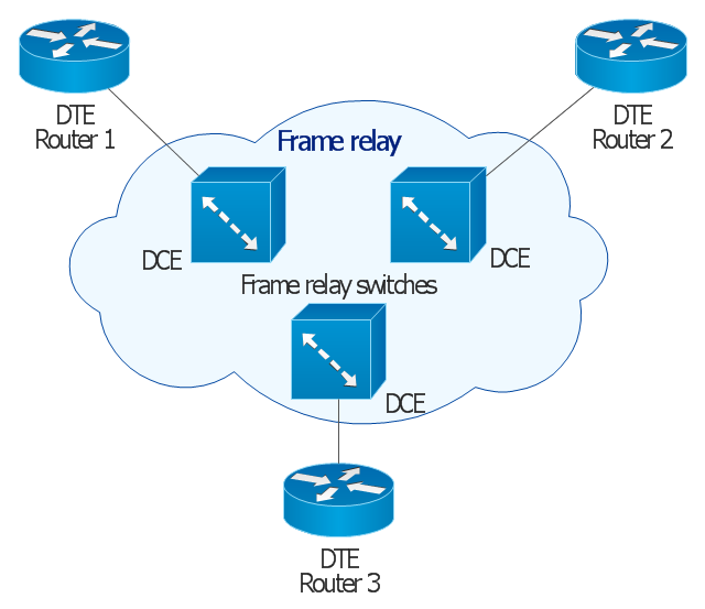
This example depicts basic network diagram of a frame relay network.
"Frame relay is a standardized wide area network technology that specifies the physical and logical link layers of digital telecommunications channels using a packet switching methodology. Originally designed for transport across Integrated Services Digital Network (ISDN) infrastructure, it may be used today in the context of many other network interfaces.
Network providers commonly implement frame relay for voice (VoFR) and data as an encapsulation technique, used between local area networks (LANs) over a wide area network (WAN). Each end-user gets a private line (or leased line) to a frame relay node. The frame relay network handles the transmission over a frequently changing path transparent to all end-user extensively used WAN protocols. It is less expensive than leased lines and that is one reason for its popularity. The extreme simplicity of configuring user equipment in a frame relay network offers another reason for frame relay's popularity.
With the advent of Ethernet over fiber optics, MPLS, VPN and dedicated broadband services such as cable modem and DSL, the end may loom for the frame relay protocol and encapsulation. However many rural areas remain lacking DSL and cable modem services. In such cases, the least expensive type of non-dial-up connection remains a 64-kbit/ s frame relay line. Thus a retail chain, for instance, may use frame relay for connecting rural stores into their corporate WAN." [Frame Relay. Wikipedia]
The Cisco network diagram example "Frame relay" was created using the ConceptDraw PRO diagramming and vector drawing software extended with the Cisco Network Diagrams solution from the Computer and Networks area of ConceptDraw Solution Park.
Cisco network diagram
This cloud computing infographic example was drawn on the base of Wikimedia Commons file: Cloud computing types.svg. [commons.wikimedia.org/ wiki/ File:Cloud_ computing_ types.svg]
This file is licensed under the Creative Commons Attribution-Share Alike 3.0 Unported license. [creativecommons.org/ licenses/ by-sa/ 3.0/ deed.en]
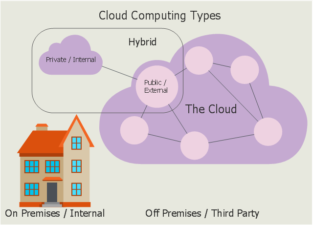
"Deployment models
Private cloud
Private cloud is cloud infrastructure operated solely for a single organization, whether managed internally or by a third-party, and hosted either internally or externally. ...
Public cloud
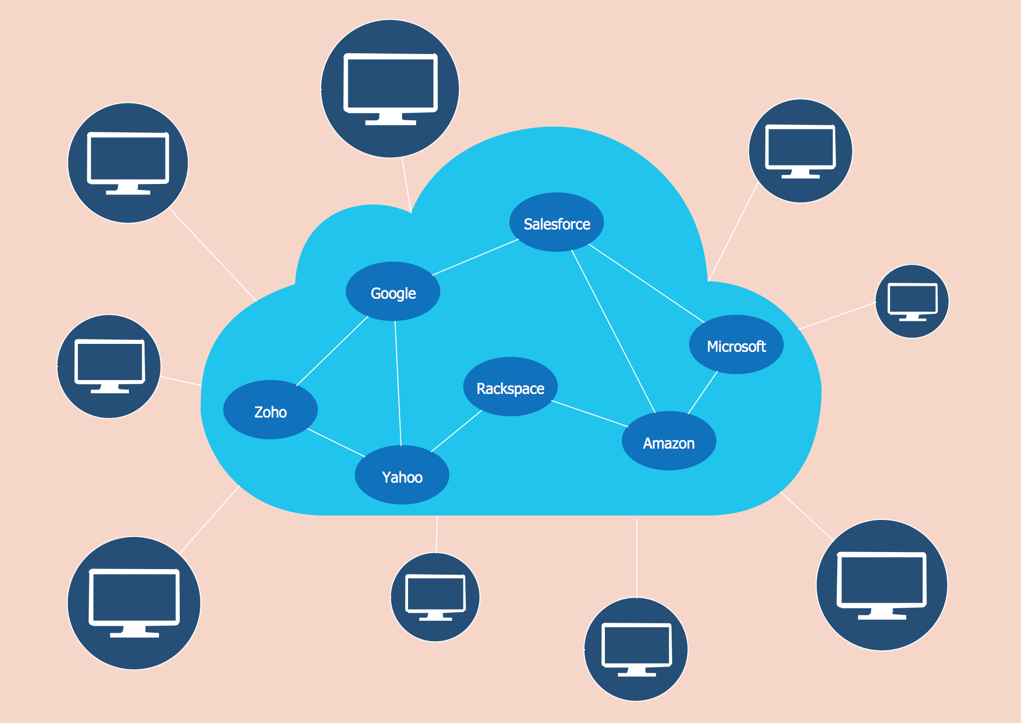
A cloud is called a "public cloud" when the services are rendered over a network that is open for public use. Public cloud services may be free. Technically there may be little or no difference between public and private cloud architecture, however, security consideration may be substantially different for services (applications, storage, and other resources) that are made available by a service provider for a public audience and when communication is effected over a non-trusted network. Generally, public cloud service providers like Amazon AWS, Microsoft and Google own and operate the infrastructure at their data center and access is generally via the Internet." [Cloud computing. Wikipedia]
The infographic example "Cloud computing types" was drawn using ConceptDraw PRO software extended with the Cloud Computing Diagrams solution from the Computer and Networks area of ConceptDraw Solution Park.
This file is licensed under the Creative Commons Attribution-Share Alike 3.0 Unported license. [creativecommons.org/ licenses/ by-sa/ 3.0/ deed.en]
"Deployment models
Private cloud
Private cloud is cloud infrastructure operated solely for a single organization, whether managed internally or by a third-party, and hosted either internally or externally. ...
Public cloud
A cloud is called a "public cloud" when the services are rendered over a network that is open for public use. Public cloud services may be free. Technically there may be little or no difference between public and private cloud architecture, however, security consideration may be substantially different for services (applications, storage, and other resources) that are made available by a service provider for a public audience and when communication is effected over a non-trusted network. Generally, public cloud service providers like Amazon AWS, Microsoft and Google own and operate the infrastructure at their data center and access is generally via the Internet." [Cloud computing. Wikipedia]
The infographic example "Cloud computing types" was drawn using ConceptDraw PRO software extended with the Cloud Computing Diagrams solution from the Computer and Networks area of ConceptDraw Solution Park.
Infographic
HelpDesk
How to Operate with Project Time Frames in ConceptDraw PROJECT

Wireframe Examples
Network Topologies


 Cisco Network Diagrams
Cisco Network Diagrams solution extends ConceptDraw DIAGRAM with the best characteristics of network diagramming software. Included samples, templates and libraries of built-in standardized vector Cisco network icons and Cisco symbols of computers, network devices, network appliances and other Cisco network equipment will help network engineers, network designers, network and system administrators, as well as other IT professionals and corporate IT departments to diagram efficiently the network infrastructure, to visualize computer networks topologies, to design Cisco computer networks, and to create professional-looking Cisco Computer network diagrams, Cisco network designs and schematics, Network maps, and Network topology diagrams in minutes.
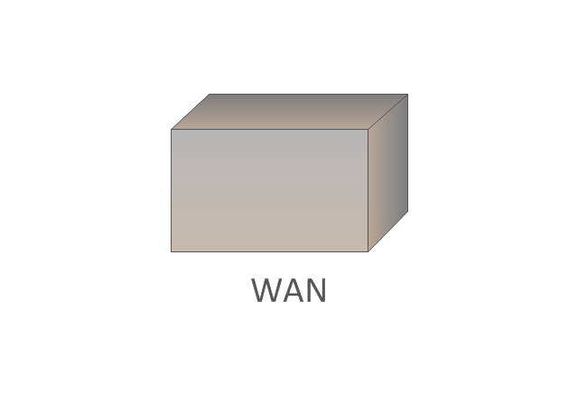
The vector stencils library "Cisco WAN" contains 15 symbols of wide area network (WAN) devices and equipment for drawing Cisco WAN diagrams.
"A wide area network (WAN) is a network that covers a broad area (i.e., any telecommunications network that links across metropolitan, regional, or national boundaries) using leased telecommunication lines. Business and government entities utilize WANs to relay data among employees, clients, buyers, and suppliers from various geographical locations. ...
Related terms for other types of networks are personal area networks (PANs), local area networks (LANs), campus area networks (CANs), or metropolitan area networks (MANs) which are usually limited to a room, building, campus or specific metropolitan area (e.g., a city) respectively.
... it may be best to view WANs as computer networking technologies used to transmit data over long distances, and between different LANs, MANs and other localised computer networking architectures. ...
WANs are often built using leased lines. At each end of the leased line, a router connects the LAN on one side with a second router within the LAN on the other. Leased lines can be very expensive. Instead of using leased lines, WANs can also be built using less costly circuit switching or packet switching methods. Network protocols including TCP/ IP deliver transport and addressing functions. Protocols including Packet over SONET/ SDH, MPLS, ATM and Frame relay are often used by service providers to deliver the links that are used in WANs." [Wide area network. Wikipedia]
The symbols example "Cisco WAN - Vector stencils library" was created using the ConceptDraw PRO diagramming and vector drawing software extended with the Cisco Network Diagrams solution from the Computer and Networks area of ConceptDraw Solution Park.
www.conceptdraw.com/ solution-park/ computer-networks-cisco
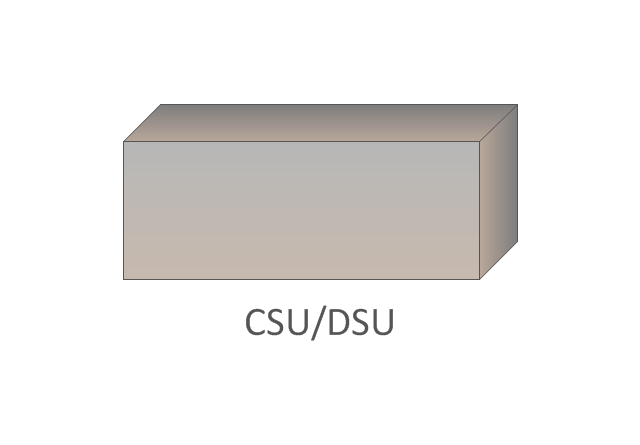
CSU/DSU
WAN
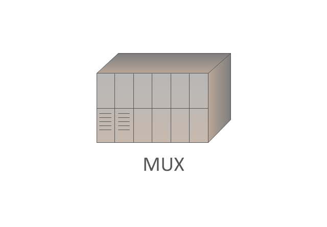
MUX
PBX switch
Hub
Hub, blue
NAT

Network cloud, dark
Network cloud, gold
Network cloud, white
Network cloud, standard color
Distributed director
Local director
PBX
DPT
EPN Frame-Relay and Dial-up Network. Computer and Network Examples

Amazon Cloud Computing Architecture
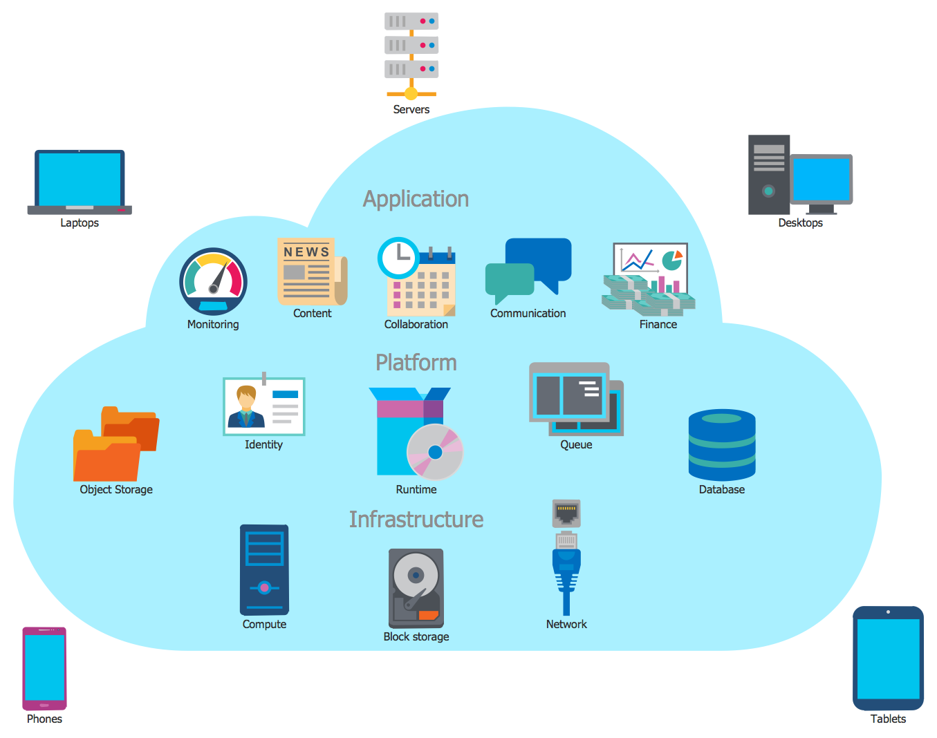
Cloud Computing Architecture
 Cloud Computing Diagrams
The Cloud Computing Diagrams solution extends the functionality of the ConceptDraw DIAGRAM diagramming software with a comprehensive collection of libraries of commonly accepted cloud computing vector stencils to help you to get started designing Cloud Computing Diagrams, Architecture Diagrams and Cloud Computing Architecture Diagrams without effort. This solution lets one professionally depict the way how the cloud computing works, allows giving a powerful introduction to the Cloud computing architecture and Amazon cloud computing architecture, to display the essence of the cloud computing, the main characteristics and classification of the cloud services thanks to the wide variety of predesigned samples and examples.
What is Cloud Computing
- Dollar Sign In Circular Frame Png Vector
- Green Frame Png
- Frame Landscape Vector Png
- Mpls Cloud Png
- Cloud Png Gray
- Back Vector Icon Png
- Png Rectangle
- Window elements - Vector stencils library | Cloud round icons ...
- Blue Cloud Png
- Simple Frame Design Png
- Business Productivity - Marketing | How to Build Cloud Computing ...
- Design elements - Advertisement | Step chart - Cloud testing steps ...
- Pbx Symbol Png
- Nat Png
- How to Build Cloud Computing Diagram Principal Cloud ...
- The Cloud Internet Access
- Finger Point Icon Png
- Nat Icon Png
- Frame relay | Cisco WAN - Vector stencils library | Logical symbols ...
- Cliparts Design Png