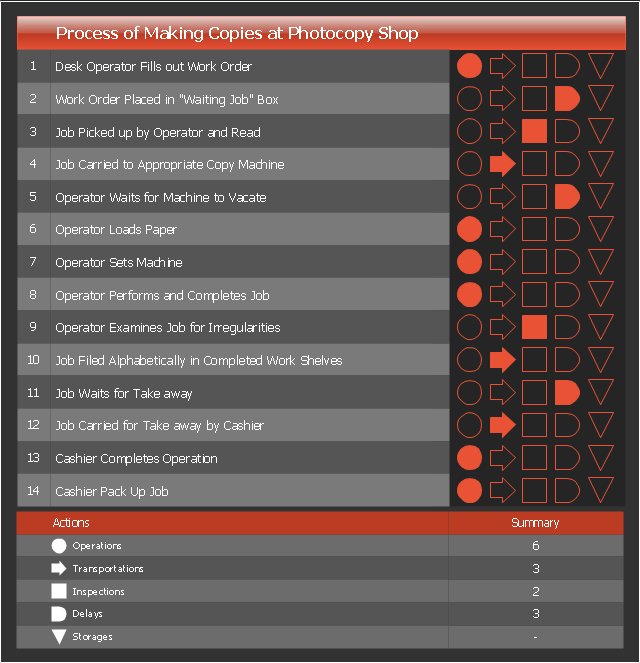
Flow process chart is used in quality control to display the action sequence of physical or manual process.
Flow process chart is useful for recording actions and documenting the production process.
Flow process chart helps to analyze and improve the process steps.
Flow process chart is more preferable than flowchart for documenting the mostly sequential processes.
Three types of flow process charts include: 1) man-type charts depicting the person actions, 2) material-type charts displaying the actions with product or material object, 3) equipment-type charts visualizing the useage of tools and equipment.
The set of symbols used in the flow process charts was developed by the American Society of Mechanical Engineers (ASME).
This flow process chart example was created using the ConceptDraw PRO diagramming and vector drawing software extended with the Matrices solution from the Marketing area of ConceptDraw Solution Park.
Flow process chart
 ConceptDraw Solution Park
ConceptDraw Solution Park collects graphic extensions, examples and learning materials
HelpDesk
How to Determine what Information to be Displayed in the Project Resource List

HelpDesk
How to Resize Objects in ConceptDraw PRO

 Rack Diagrams
Rack Diagrams solution extends ConceptDraw PRO software with samples, templates and libraries of vector stencils for drawing the computer network server rack mounting diagrams.
HelpDesk
How to Create a Wireless Network Diagram

 Wireless Networks
The Wireless Networks Solution extends ConceptDraw PRO software with professional diagramming tools, set of wireless network diagram templates and samples, comprehensive library of wireless communications and WLAN objects to help network engineers and designers efficiently design and create Wireless network diagrams that illustrate wireless networks of any speed and complexity, and help to identify all required equipment for construction and updating wireless networks, and calculating their costs.
 Computer and Networks Area
The solutions from Computer and Networks Area of ConceptDraw Solution Park collect samples, templates and vector stencils libraries for drawing computer and network diagrams, schemes and technical drawings.
 Mechanical Engineering
This solution extends ConceptDraw PRO v.9 mechanical drawing software (or later) with samples of mechanical drawing symbols, templates and libraries of design elements, for help when drafting mechanical engineering drawings, or parts, assembly, pneumatic,
 Office Layout Plans
Office layouts and office plans are a special category of building plans and are often an obligatory requirement for precise and correct construction, design and exploitation office premises and business buildings. Designers and architects strive to make office plans and office floor plans simple and accurate, but at the same time unique, elegant, creative, and even extraordinary to easily increase the effectiveness of the work while attracting a large number of clients.
HelpDesk
How to Create a Floor Plan for the Classroom

- Flow process chart
- Equipment Type Flow Process Type
- Flow process chart | Difference In Man Type And Material Type Of ...
- Process Flowchart | Work Flow Diagrams with ConceptDraw PRO ...
- Types of Flowchart - Overview | Process Flowchart | Cross ...
- Basic Flowchart Symbols | Flow Chart Symbols | Process Flowchart ...
- Flow process chart | Matrices | Cross-Functional Flowchart ...
- Types of Flowchart - Overview | Flow process chart | Flow process ...
- Flow process chart | Process flow diagram template | Cross ...
- Flow process chart | Examples Of Man Type Flow Process Chart
- Cross-Functional Process Map Template | Flow process chart | TQM ...
- Flow process chart | Network Glossary Definition | Man Type Flow ...
- Cross Functional Flowchart Examples | Types of Flowchart ...
- Flow Process Chart Man Type Examples
- Fishbone diagram - Production process | Total Quality Management ...
- Flow Chart Diagram Examples | Cross-Functional Flowcharts ...
- Flow process chart | Types of Flowchart - Overview | Types of ...
- Process Flowchart | Cross-Functional Flowcharts | How to Simplify ...
- Flow Process Chart Material Type
- Flowchart Software | Flow process chart | Workflow Diagram ...