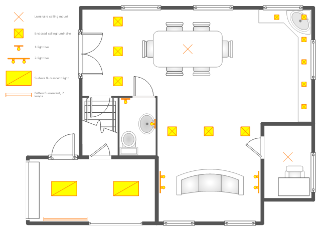
This electrical floor plan sample shows the lighting and switch layout.
"In building wiring, a light switch is a switch, most commonly used to operate electric lights, permanently connected equipment, or electrical outlets. Portable lamps such as table lamps will have a light switch mounted on the socket, base, or in-line with the cord. Manually operated on/ off switches may be substituted by remote control switches, or light dimmers that allow controlling the brightness of lamps as well as turning them on or off. Light switches are also found in flashlights and automobiles and other vehicles." [Light switch. Wikipedia]
The electrical floor plan example "Lighting and switch layout" was created using the ConceptDraw PRO diagramming and vector drawing software extended with the Electric and Telecom Plans solution from the Building plans area of ConceptDraw Solution Park.
Electrical floor plan

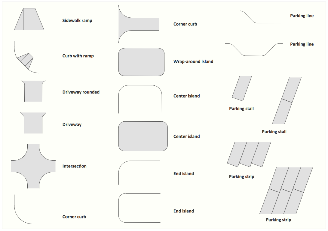
Electrical Symbols — Lamps, Acoustics, Readouts

The vector stencils library "Lighting" contains 55 symbols of lighting devices and equipment.
Use these shapes for drawing lighting design floor plans, circuit schematic and wiring diagrams, cabling layouts, and reflected ceiling plans in the ConceptDraw PRO diagramming and vector drawing software.
The vector stencils library "Lighting" is included in the Electric and Telecom Plans solution from the Building Plans area of ConceptDraw Solution Park.
Luminaire ceiling mount

Enclosed ceiling luminaire

Wall light

Down lighter

Outdoor lightning

Outdoor lightning, bollard

1-light bar

2-light bar

4-light bar

6-light bar

8-light bar

Batten fluorescent, 1 lamp

Batten fluorescent, 2 lamps

Batten fluorescent, 3 lamps

Batten fluorescent, 4 lamps

Surface Fluorescent Light

Modular fluorescent fitting

Modular fluorescent fitting, inverter

Modular fluorescent fitting 2

Emergency light

Emergency light 2

Emergency sign

Emergency Light, Recessed

Light, Surface Mounted

Ceiling Light Outlet

Recessed Ceiling Light

Ceiling Fan

Ceiling Light with Pull Cord

Weatherproof Landscape Light

Wall Light Outlet

Control Keypad

Emergency Battery Unit

Emergency Battery Unit with two Lights

Emergency Single Light, Remote Mounted

Emergency Duplex Light, Remote Mounted

Spotlight, Single Head

Spotlight, Double Head

Exit Sign, Pendant Mounted

Exit Sign, Wall Mounted

Light, Pole Mounted

Light Flood, Pole Mounted

Light Flood, Wall Mounted

Light, Stanchion Mounted

Twin Lights, Pendant Mounted

Inground Light, Floor Mounted

Suspended Light

Suspended Lights

Integrated Light

Lights, Track Mounted

Night Light

Roadway Light, Cobra Head

Louvers

Light, Directional Accent

Light, Directional Aiming Line

Light, Directional Arrow
Interior Design. Site Plan — Design Elements
How To use House Electrical Plan Software


Samples of Flowchart

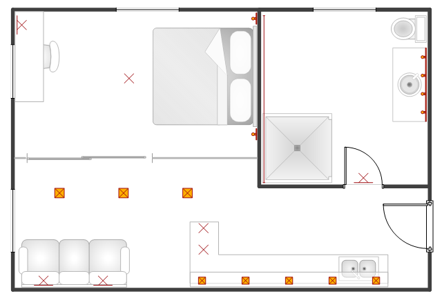
This reflected ceiling plan (RCP) sample depicts the ground floor lighting scheme.
"Downlighting is most common, with fixtures on or recessed in the ceiling casting light downward. This tends to be the most used method, used in both offices and homes. Although it is easy to design it has dramatic problems with glare and excess energy consumption due to large number of fittings. The introduction of LED lighting has greatly improved this by approx. 90% when compared to a halogen downlight or spotlight. LED lamps or bulbs are now available to retro fit in place of high energy consumption lamps.
" [Lighting. Wikipedia]
The lighting scheme example "Ground floor RCP" was created using the ConceptDraw DIAGRAM diagramming and vector drawing software extended with the Reflected Ceiling Plans solution from the Building Plans area of ConceptDraw Solution Park.
Lighting sheme
Building Drawing. Design Element Site Plan


How To use Electrical and Telecom Plan Software

This flat reflected ceiling plan (RCP) sample represents the light fixtures layout.
"A light fixture (US English), light fitting (UK English), or luminaire is an electrical device used to create artificial light by use of an electric lamp. All light fixtures have a fixture body and a light socket to hold the lamp and allow for its replacement. Fixtures may also have a switch to control the light. Fixtures require an electrical connection to a power source; permanent lighting may be directly wired, and moveable lamps have a plug." [Light fixture. Wikipedia]
The lighting scheme example "Flat RCP" was created using the ConceptDraw DIAGRAM diagramming and vector drawing software extended with the Reflected Ceiling Plans solution from the Building Plans area of ConceptDraw Solution Park.
Lighting scheme
- Drawing Of Lamp In Floor Plan
- Floor Lamp Symbol On A Floor Plan
- Classroom lighting - Reflected ceiling plan | Reflected ceiling plan ...
- Furniture - Vector stencils library | Lighting and switch layout ...
- How to Create a Reflected Ceiling Floor Plan | Lighting - Vector ...
- Symbols Used In Site Development Plan Lamp Post
- Lighting and switch layout | Classroom lighting - Reflected ceiling ...
- How to Create a Reflected Ceiling Floor Plan | Reflected Ceiling ...
- Lamp Floor Plan Symbol
- Interior Design Office Layout Plan Design Element | Lighting and ...