This site uses cookies. By continuing to browse the ConceptDraw site you are agreeing to our Use of Site Cookies.

Network Security Architecture Diagram

Network Security Architecture Diagram visually reflects the network's structure and construction, and all actions undertaken for ensuring the network security which can be executed with help of software resources and hardware devices. You dream to find powerful software for easy designing Network Security Architecture Diagram? We recommend to use ConceptDraw DIAGRAM extended with Network Security Diagrams Solution from the Computer and Networks Area of ConceptDraw Solution Park.

Amazon Web Services, AWS, Amazon cloud AWS Architecture Diagrams

Amazon Web Services, AWS, Amazon cloud
AWS Architecture Diagrams with powerful drawing tools and numerous predesigned Amazon icons and AWS simple icons is the best for creation the AWS Architecture Diagrams, describing the use of Amazon Web Services or Amazon Cloud Services, their application for development and implementation the systems running on the AWS infrastructure. The multifarious samples give you the good understanding of AWS platform, its structure, services, resources and features, wide opportunities, advantages and benefits from their use; solution’s templates are essential and helpful when designing, description and implementing the AWS infrastructure-based systems. Use them in technical documentation, advertising and marketing materials, in specifications, presentation slides, whitepapers, datasheets, posters, etc.

microsoft azure, windows azure, azure management, azure storage, azure blob storage, azure services Azure Architecture

microsoft azure, windows azure, azure management, azure storage, azure blob storage, azure services
Azure Architecture solution bundles into one handy tool everything you need to create effective Azure Architecture diagrams. It adds the extra value to versatile ConceptDraw DIAGRAM software and extends the users capabilities with comprehensive collection of Microsoft Azure themed graphics, logos, preset templates, wide array of predesigned vector symbols that covers the subjects such as Azure management, Azure storage, and Azure services, amongst others, and allow you to illustrate Azure Architecture diagrams at any degree of complexity, to present visually your Azure cloud system architecture with professional style, to design Azure cloud topology, to document Windows Azure Architecture and Azure Cloud System Architecture, to visualize the great abilities and work of Microsoft Azure Cloud System and Azure services.

Control and Information Architecture Diagrams (CIAD) with ConceptDraw DIAGRAM

One of the three main constituents of any enterprise is the Control and Information Architecture. The rest two are Production facilities and People and Organization.

ER Diagram for Cloud Computing

The entity–relationship (ER) model is a data model that lets graphically represent the information system and depict the relationships between people, objects, concepts, places, and events within a given system. It is also convenient to use the ER Diagram for Cloud computing representation and description the Cloud computing architecture, design them with pleasure using the extensive tools of the Cloud Computing Diagrams solution from the Computers and Network area of ConceptDraw Solution Park.

AWS Simple Icons for Architecture Diagrams

The AWS Architecture Diagrams solution includes icons, sample and templates for several Amazon Web Services products and resources, to be used when creating architecture diagrams. The icons are designed to be simple so that you can easily incorporate them in your diagrams and put them in your whitepapers, presentations, datasheets, posters or any technical material you like.
HelpDesk

How to Make a UML Diagram

The Unified Modeling Language™(UML) is a standard visual modeling language to document business processes and software architecture. UML uses several types of diagrams including Use Case Diagrams, Class, Package, Component, Composite Structure Diagrams, Deployments, Activities, and Interactions. The accepted standard used when modeling a system is known as the Unified Modeling Language (UML), a generic set of notations that are used when creating UML diagrams. These notations can visually represent requirements, subsystems, logical and physical elements, and structural and behavioral patterns, that are especially relevant to systems built using an object-oriented style.
Using UML during the modeling process has a number of benefits — for one, the entire development team can share information and collaborate using a common language, diagrams, and software, something that's not possible when using a more task-specific programming language.

Restaurant Floor Plans Samples

Whether you already started or just planning to open a restaurant, first you have to design the place itself. Sounds complex? No worries, we are here to help.
ConceptDraw for successfully planning your restaurant floor plans. That tool can help you to plan what you will require.
The software includes sample: restaurant floor and cafe plans, restaurant floor plan layout, restaurant design, restaurant electrical plan, restaurant emergency plans, restaurant landscape design.

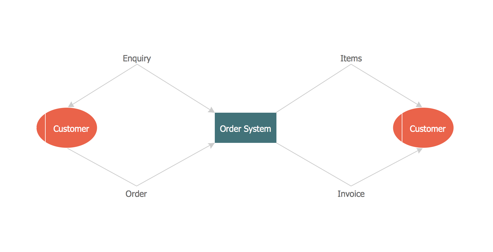
Data Flow Diagram (DFD)

This example is created using ConceptDraw DIAGRAM enhanced with solution Data Flow Diagrams. This diagram shows one of the business processes to simplify and accelerate understanding, analysis, and representation.

Data flow Model Diagram

This sample was created in ConceptDraw DIAGRAM diagramming and vector drawing software using the Data Flow Diagrams Solution from the Software Development area of ConceptDraw Solution Park.
This sample shows the Data Flow Model Diagram that displays the Order system and the interactions between the Order system and Customers.