"Logical topology, or signal topology, is the arrangement of devices on a computer network and how they communicate with one another. How devices are connected to the network through the actual cables that transmit data, or the physical structure of the network, is called the physical topology. Physical topology defines how the systems are physically connected. It represents the physical layout of the devices on the network. The logical topology defines how the systems communicate across the physical topologies.
Logical topologies are bound to network protocols and describe how data is moved across the network. ...
EXAMPLE : twisted pair Ethernet is a logical bus topology in a physical star topology layout. while IBM's token ring is a logical ring topology, it is physically set up in star topology." [Logical topology. Wikipedia]
This Cisco logical computer network diagram example was created using the ConceptDraw PRO diagramming and vector drawing software extended with the Cisco Network Diagrams solution from the Computer and Networks area of ConceptDraw Solution Park.
HelpDesk
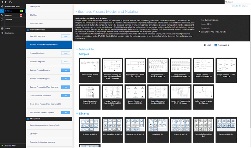
ConceptDraw Office for Apple macOS Installation Definition
With the introduction of version 3, ConceptDraw Office has been redesigned to better accommodate future developments and solution plugins. ConceptDraw Office 3 includes ConceptDraw PRO 10, ConceptDraw MINDMAP 8, and ConceptDraw PROJECT 7. The renewed ConceptDraw STORE helps user manage downloads of ConceptDraw products and solutions. The following article provides owners of the previous versions of ConceptDraw products with important information on updating on ConceptDraw Office v3.HelpDesk
ConceptDraw Office for Windows Installation Definition
With the introduction of version 3, ConceptDraw Office has been redesigned to better accommodate future developments and solution plugins. ConceptDraw Office 3 includes ConceptDraw PRO 10, ConceptDraw MINDMAP 8, and ConceptDraw PROJECT 7. Owners of ConceptDraw Office v1 and ConceptDraw Office v2, please read this description of the specific features of the ConceptDraw Office 3 installation for Windows before updating.HelpDesk
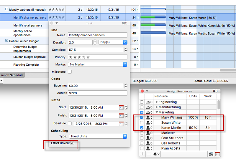
How to Use the Effort-Driven Scheduling Method
Effort-driven scheduling is the default method of project scheduling in ConceptDraw PROJECT.The vector stencils library "Network layout floorplan" contain 34 symbol icons for drawing computer network floor plans, communication equipment layouts, and structured cabling diagrams.
"Structured cabling is building or campus telecommunications cabling infrastructure that consists of a number of standardized smaller elements (hence structured) called subsystems. ...
Structured cabling design and installation is governed by a set of standards that specify wiring data centers, offices, and apartment buildings for data or voice communications using various kinds of cable, most commonly category 5e (CAT-5e), category 6 (CAT-6), and fibre optic cabling and modular connectors. These standards define how to lay the cabling in various topologies in order to meet the needs of the customer, typically using a central patch panel (which is normally 19 inch rack-mounted), from where each modular connection can be used as needed. Each outlet is then patched into a network switch (normally also rack-mounted) for network use or into an IP or PBX (private branch exchange) telephone system patch panel." [Structured cabling. Wikipedia]
The design elements example "Network layout floorplan - Vector stencils library" was created using the ConceptDraw PRO diagramming and vector drawing software extended with the Network Layout Floor Plans solution from the Computer and Networks area of ConceptDraw Solution Park.
HelpDesk
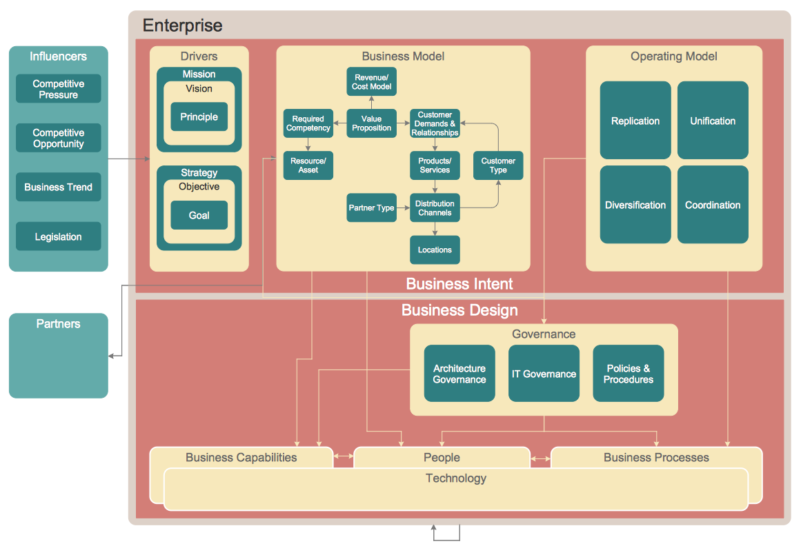
How to Create an Enterprise Architecture Diagram in ConceptDraw PRO
An Enterprise Architecture (EA) diagram is used to display the structure and operations of an organization.It is used to analyze and document an organization and its business functions, along with the applications and systems on which they are implemented. The aim of an enterprise architecture diagram is to determine how an organization can effectively achieve its current and future objectives. The Enterprise Architecture often uses diagrams to support the decision-making process. ConceptDraw PRO allows you to design Enterprise Architecture diagrams of any complexity.HelpDesk
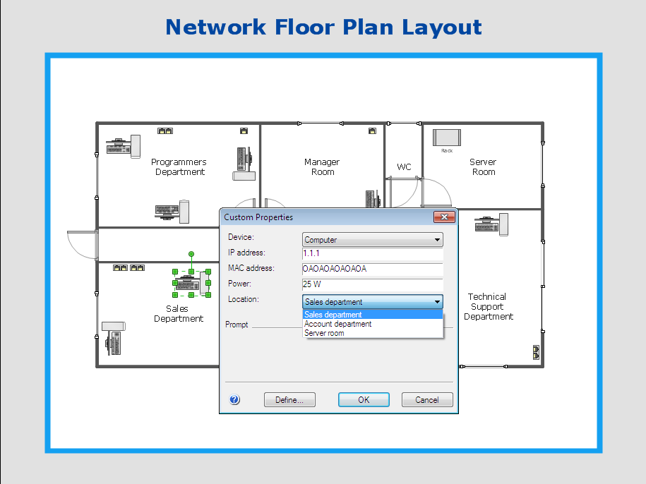
How to Work with Custom Properties in ConceptDraw PRO on PC
ConceptDraw PRO can store additional, user-defined data that can be assigned to a particular shape. This data is stored in the Custom Properties options.HelpDesk
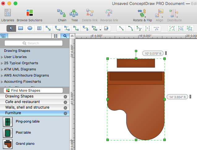
How to Change Measurement Units in ConceptDraw Drawing
ConceptDraw PRO allows you to work with drawings with many different measurement units.- Complete Network Topology | Fully Connected Network Topology ...
- Star Network Topology | 10Base-T star topology - Network diagram ...
- Tree Network Topology Diagram | Fully Connected Network ...
- Fully Connected Network Topology Diagram | Star Network ...
- Star Network Topology
- Network Topologies | Fully Connected Network Topology Diagram ...
- Star Network Topology | Bus Network Topology | Network Glossary ...
- Star Network Topology Definition
- Network Topologies | Network Glossary Definition | Design elements ...
- Hotel Network Topology Diagram | Wireless access point - Network ...
- Fully Connected Network Topology Diagram | Network Glossary ...
- Logical network topology diagram | Network Topologies | Network ...
- Tree Network Topology Diagram | Network Glossary Definition ...
- Complete Network Topology | Fully Connected Network Topology ...
- Fully Connected Network Topology Diagram | Network Glossary ...
- Wireless Network Topology | Fully Connected Network Topology ...
- Flowchart Definition | Basic Flowchart Symbols and Meaning ...
- Tree Network Topology Diagram | Network Glossary Definition ...
- Network Topologies | Fully Connected Network Topology Diagram ...
- Wireless Topology Definition

