"A bus network is a network topology in which nodes are connected in a daisy chain by a linear sequence of buses. ...
The bus is the data link in a bus network. The bus can only transmit data in one direction, and if any network segment is severed, all network transmission ceases.
A host on a bus network is called a station or workstation. In a bus network, every station receives all network traffic, and the traffic generated by each station has equal transmission priority. Each network segment is, therefore, a collision domain. In order for nodes to transmit on the same cable simultaneously, they use a media access control technology such as carrier sense multiple access (CSMA) or a bus master." [Bus network. Wikipedia]
The bus network topology diagram example was created using the ConceptDraw PRO diagramming and vector drawing software extended with the Computer and Networks solution from the Computer and Networks area of ConceptDraw Solution Park.
Bus topology

 Computer Network Diagrams
Computer Network Diagrams solution extends ConceptDraw PRO software with samples, templates and libraries of vector icons and objects of computer network devices and network components to help you create professional-looking Computer Network Diagrams, to plan simple home networks and complex computer network configurations for large buildings, to represent their schemes in a comprehensible graphical view, to document computer networks configurations, to depict the interactions between network's components, the used protocols and topologies, to represent physical and logical network structures, to compare visually different topologies and to depict their combinations, to represent in details the network structure with help of schemes, to study and analyze the network configurations, to communicate effectively to engineers, stakeholders and end-users, to track network working and troubleshoot, if necessary.
The vector stencils library "Network layout floorplan" contain 34 symbol icons for drawing computer network floor plans, communication equipment layouts, and structured cabling diagrams.
"Structured cabling is building or campus telecommunications cabling infrastructure that consists of a number of standardized smaller elements (hence structured) called subsystems. ...
Structured cabling design and installation is governed by a set of standards that specify wiring data centers, offices, and apartment buildings for data or voice communications using various kinds of cable, most commonly category 5e (CAT-5e), category 6 (CAT-6), and fibre optic cabling and modular connectors. These standards define how to lay the cabling in various topologies in order to meet the needs of the customer, typically using a central patch panel (which is normally 19 inch rack-mounted), from where each modular connection can be used as needed. Each outlet is then patched into a network switch (normally also rack-mounted) for network use or into an IP or PBX (private branch exchange) telephone system patch panel." [Structured cabling. Wikipedia]
The design elements example "Network layout floorplan - Vector stencils library" was created using the ConceptDraw PRO diagramming and vector drawing software extended with the Network Layout Floor Plans solution from the Computer and Networks area of ConceptDraw Solution Park.
PC

Scanner

Switch

Router

Modem

Hub

Rack Mount

Printer

Floor Mounted Outlet

Single Outlet

Duplex Outlet

Direct bus cable

Tops or bottoms bus cable

Side to side bus cable

Multi-tree bus cable

Bottom to side bus cable

Sides bus cable

Door

Door, threshold

Door, stop

Door, stop, threshold

Door, frame

Door, frame, threshold

Door, frame, stop

Door, frame, stop, threshold

Window

Window, sill

Window, sash

Window, sash, sill

Window, frame

Window, frame, sill

Window, frame, sash

Window, frame, sash, sill

"Network topology is the arrangement of the various elements (links, nodes, etc.) of a computer network. Essentially, it is the topological structure of a network, and may be depicted physically or logically. Physical topology refers to the placement of the network's various components, including device location and cable installation, while logical topology shows how data flows within a network, regardless of its physical design. Distances between nodes, physical interconnections, transmission rates, and/ or signal types may differ between two networks, yet their topologies may be identical. The study of network topology recognizes eight basic topologies: Point-to-point, Bus, Star, Ring or circular, Mesh, Tree, Hybrid, Daisy chain." [Network topology. Wikipedia]
The computer network topologies diagram example was created using the ConceptDraw PRO diagramming and vector drawing software extended with the Computer and Networks solution from the Computer and Networks area of ConceptDraw Solution Park.
The computer network topologies diagram example was created using the ConceptDraw PRO diagramming and vector drawing software extended with the Computer and Networks solution from the Computer and Networks area of ConceptDraw Solution Park.
Network topologies

The vector stencils library "Logical symbols" contains 49 logical symbols for drawing logical network topology diagrams.
"Logical topology, or signal topology, is the arrangement of devices on a computer network and how they communicate with one another. How devices are connected to the network through the actual cables that transmit data, or the physical structure of the network, is called the physical topology. Physical topology defines how the systems are physically connected. It represents the physical layout of the devices on the network. The logical topology defines how the systems communicate across the physical topologies.
Logical topologies are bound to network protocols and describe how data is moved across the network. ... EXAMPLE : twisted pair Ethernet is a logical bus topology in a physical star topology layout. While IBM's token ring is a logical ring topology, it is physically set up in star topology." [Logical topology. Wikipedia]
The icons example "Logical symbols - Vector stencils library" was created using the ConceptDraw PRO diagramming and vector drawing software extended with the Computer and Networks solution from the Computer and Networks area of ConceptDraw Solution Park.
www.conceptdraw.com/ solution-park/ computer-and-networks
Coaxial Line Tag

Fiber Optic Line Tag

Twisted Pair Line Tag

SC2200 Signaling Controller

Bridge

Network Management Appliance

Access Server (Communications Server)
-logical-symbols---vector-stencils-library.png--diagram-flowchart-example.png)
Terminal Server

Web Browser

Security Management, Cisco

Lock and Key

Lock

Key

Relational Database

Host

CSU/DSU

WAN

University

Government building

Home Office

Telecommuter House PC

Medium Building, Regular

Headquarters, Subdued

House, Regular

Small Business

Network Connector

Dynamic Connector

Line Connector

Line-curve Connector

Bus

FDDI Ring

Peer-to-peer

Token-ring

Star

Comm-link

Curved Bus

Ethernet

Cloud

Speaker

Microphone

Router

ATM Router

ISDN Switch

ATM Switch

ATM/FastGB Etherswitch

Workgroup Switch

Small Hub

100BaseT Hub

CDDI-FDDI

The vector stencils library "Computer network" contains 51 symbols of computer network devices and equipment for drawing computer network diagrams.
"Network Mapping Software.
A number of software tools exist to design computer network diagrams / or generate visual maps of networks, servers, storage, services, data centers, and other peripherals. Broadly, there are two types of software tools - those that help create diagrams manually and those that generate them using automated / semi-automated approaches.
Type of Software.
(1) Manual - allows users to design and draw logical and physical topology diagrams by manually placing icons and connections.
(2) Automated - generate topology diagrams / maps by traversing the network and automatically discovering resident devices or by importing network data." [Comparison of network diagram software. Wikipedia]
ConceptDraw PRO is the software for manual design of computer network diagrams. The solutions of the Computer and Networks area in ConceptDraw Solution Park extend ConceptDraw PRO with vector stencils libraries, templates and examples for creating the computer network diagrams.
The symbols example "Computer network - Vector stencils library" was created using the ConceptDraw PRO diagramming and vector drawing software extended with the Computer and Networks solution from the Computer and Networks area of ConceptDraw Solution Park.
www.conceptdraw.com/ solution-park/ computer-and-networks
Laptop

Desktop computer

Firewall

Bus

Ethernet

Star network

FDDI Ring

Token-ring

Comm-link

Modem

Laser printer

Inkjet printer

Image scanner

City

Ethernet hub

Wireless router

Network switch

iPod Classic

iPhone/ iPod Touch

Xserve RAID

XServe

Apple Thunderbolt Display

Data store

Mac Pro

iMac

RAID

Mainframe

Rack-mountable server

Server

PDA

Cloud

Computer monitor

Workstation

Router

IP Phone

Fax

Mobile phone

Smartphone

Compact Disk

Mouse

Apple Wireless Mouse

Computer keyboard

Apple Keyboard

Radio tower

Satellite dish

Satellite

Webcam

AirPort Extreme

Airport Express

MacBook

iPhone 4

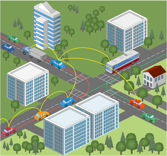
This vehicular network diagram sample was drawn on the base of picture illustrating the post "Intelligent transportation system" from the blog "Technology New Here".
"Intelligent transportation systems are projects that aim to integrate modern communication and information technology into existing transportation management systems in order to optimize vehicle life, fuel efficiency, safety, and traffic in urbanized cities.
The need for intelligent transportation systems stems from the fact that traffic congestion has been increasing all around the world because of increasing population, increasing amount of transportation vehicles and increasing urbanization."
[technologynewhere.wordpress.com/ 2010/ 05/ 12/ intelligent-transportation-system/ ]
The vehicular network diagram example "Intelligent transportation system" was created using the ConceptDraw PRO diagramming and vector drawing software extended with the Vehicular Networking solution from the Computer and Networks area of ConceptDraw Solution Park.
Vehicular network diagram
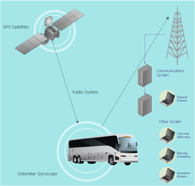
This vehicular network diagram example was drawn on the base of picture illustrating the article "Automatic Vehicle Location: Rural Transit" from the website of the Research and Innovative Technology Administration (RITA), U.S. Department of Transportation (US DOT).
"Automatic Vehicle Location (AVL) systems calculate the real-time location of any vehicle equipped with a Global Positioning Satellite (GPS) receiver. Data are then transmitted to the transit center with use of radio or cellular communications and can be used immediately for daily operations as well as archived for further analysis.
As a stand-alone technology, an AVL system can be used to monitor on-time performance. When combined with other technologies, AVL can deliver many benefits in the areas of fleet management, service planning, safety and security, traveler information, fare payment, vehicle component monitoring, and data collection. Since the greatest benefits from AVL are achieved by combining it with other Intelligent Transportation System (ITS) technologies, AVL is most appropriate for large rural agencies with more than 30 vehicles that plan to implement a comprehensive ITS."
[pcb.its.dot.gov/ factsheets/ avl/ avlRural_ overview.asp]
The vehicular network diagram example "Automatic vehicle location" was created using the ConceptDraw PRO diagramming and vector drawing software extended with the Vehicular Networking solution from the Computer and Networks area of ConceptDraw Solution Park.
Vehicular network diagram
Used Solutions
"Logical topology, or signal topology, is the arrangement of devices on a computer network and how they communicate with one another. How devices are connected to the network through the actual cables that transmit data, or the physical structure of the network, is called the physical topology. Physical topology defines how the systems are physically connected. It represents the physical layout of the devices on the network. The logical topology defines how the systems communicate across the physical topologies.
Logical topologies are bound to network protocols and describe how data is moved across the network. ...
EXAMPLE : twisted pair Ethernet is a logical bus topology in a physical star topology layout. while IBM's token ring is a logical ring topology, it is physically set up in star topology." [Logical topology. Wikipedia]
This Cisco logical computer network diagram example was created using the ConceptDraw PRO diagramming and vector drawing software extended with the Cisco Network Diagrams solution from the Computer and Networks area of ConceptDraw Solution Park.
Logical network topology diagram

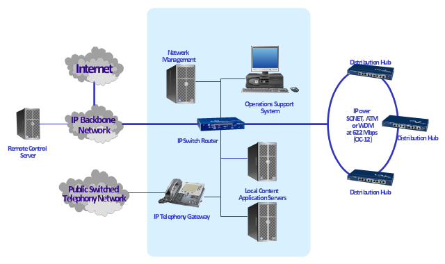
"A cable television headend is a master facility for receiving television signals for processing and distribution over a CATV system. The headend facility is normally unstaffed and surrounded by some type of security fencing and is typically a building or large shed housing electronic equipment used to receive and re-transmit video over the local cable infrastructure. One can also find head ends in power line communication (PLC) substations and Internet communications networks." [Cable television headend. Wikipedia]
This regional cable head-end diagram example was created using the ConceptDraw PRO diagramming and vector drawing software extended with the Computer and Networks solution from the Computer and Networks area of ConceptDraw Solution Park.
This regional cable head-end diagram example was created using the ConceptDraw PRO diagramming and vector drawing software extended with the Computer and Networks solution from the Computer and Networks area of ConceptDraw Solution Park.
Network diagram
The vector stencils library "Network layout floorplan" contain 34 symbol icons for drawing computer network floor plans and communication equipment and cabling layouts.
"Networking hardware may also be known as network equipment or computer networking devices. Units which are the last receiver or generate data are called hosts or data terminal equipment.
All these terms refer to devices facilitating the use of a computer network. Specifically, they mediate data in a computer network. ...
Typically, networking hardware includes gateways, routers, network bridges, switches, hubs, and repeaters. But it also includes hybrid network devices such as multilayer switches, protocol converters, bridge routers, proxy servers, firewalls, network address translators, multiplexers, network interface controllers, wireless network interface controllers, modems, ISDN terminal adapters, line drivers, wireless access points, networking cables and other related hardware.
The most common kind of networking hardware today is a copper-based Ethernet adapter because of its standard inclusion on most modern computer systems. Wireless networking has, however, become increasingly popular, especially for portable and handheld devices.
Other hardware prevalent in computer networking includes data center equipment (such as file servers, database servers and storage areas), network services (such as DNS, DHCP, email, etc.) as well as devices which assure content delivery." [Networking hardware. Wikipedia]
The shapes example "Design elements - Network layout floorplan" was created using the ConceptDraw PRO diagramming and vector drawing software extended with the Network Layout Floor Plans solution from the Computer and Networks area of ConceptDraw Solution Park.
Network layout floor plan symbols

"The Ethernet physical layer is the physical layer component of the Ethernet family of computer network standards.
The Ethernet physical layer evolved over a considerable time span and encompasses quite a few physical media interfaces and several magnitudes of speed. The speed ranges from 1 Mbit/ s to 100 Gbit/ s, while the physical medium can range from bulky coaxial cable to twisted pair and optical fiber. In general, network protocol stack software will work similarly on all physical layers.
10-gigabit Ethernet was already used in both enterprise and carrier networks by 2007, with 40 Gbit/ s and 100 Gbit/ s Ethernet ratified. ...
Many Ethernet adapters and switch ports support multiple speeds, using autonegotiation to set the speed and duplex for the best values supported by both connected devices. If auto-negotiation fails, a multiple-speed device will sense the speed used by its partner, but will assume half-duplex. A 10/ 100 Ethernet port supports 10BASE-T and 100BASE-TX. A 10/ 100/ 1000 Ethernet port supports 10BASE-T, 100BASE-TX, and 1000BASE-T." [Ethernet physical layer. Wikipedia]
The LAN equipment and cabling layout floorplan example "Ethernet local area network layout floor plan" was created using the ConceptDraw PRO diagramming and vector drawing software extended with the Network Layout Floor Plans solution from the Computer and Networks area of ConceptDraw Solution Park.
Ethernet LAN layout floorplan

The vector stencils library "Cisco LAN" contains 23 symbols of local area network (LAN) devices and equipment for drawing Cisco LAN topology diagrams.
"Network topology describes the layout of interconnections between devices and network segments. At the Data Link Layer and Physical Layer, a wide variety of LAN topologies have been used, including ring, bus, mesh and star, but the most common LAN topology in use today is switched Ethernet. At the higher layers, the Internet Protocol (TCP/ IP) has become the standard, replacing NetBEUI, IPX/ SPX, AppleTalk and others.
Simple LANs generally consist of one or more switches. A switch can be connected to a router, cable modem, or ADSL modem for Internet access. Complex LANs are characterized by their use of redundant links with switches using the spanning tree protocol to prevent loops, their ability to manage differing traffic types via quality of service (QoS), and to segregate traffic with VLANs. A LAN can include a wide variety of network devices such as switches, firewalls, routers, load balancers, and sensors.
LANs can maintain connections with other LANs via leased lines, leased services, or the Internet using virtual private network technologies. Depending on how the connections are established and secured in a LAN, and the distance involved, a LAN may also be classified as a metropolitan area network (MAN) or a wide area network (WAN)." [Local area network. Wikipedia]
The symbols example "Cisco LAN - Vector stencils library" was created using the ConceptDraw PRO diagramming and vector drawing software extended with the Cisco Network Diagrams solution from the Computer and Networks area of ConceptDraw Solution Park.
www.conceptdraw.com/ solution-park/ computer-networks-cisco
Sun workstation

Workstation

PC

Macintosh

Terminal

Mini VAX

Printer

Laptop

File server

Monitor

Web cluster

ATM fast gigabit etherswitch

HP Mini

Supercomputer

LAN2LAN

LAN to LAN

Web server

Web browser

Repeater

PDA

General appliance

PC, blue

Mini VAX, blue

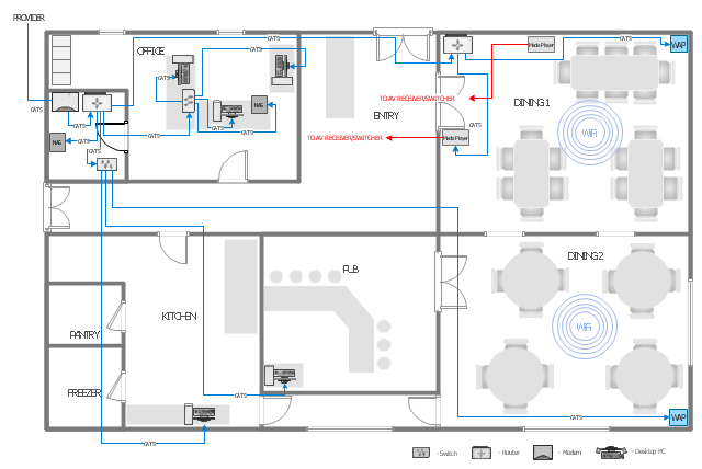
This computer network layout floorplan was drawn on the base of the picture from the Media Institute blog of the Madison Media Institute.
[mediainstitute.edu/ media-schools-blog/ wp-content/ uploads/ 2012/ 01/ floor_ plan.png]
The example "Restaurant network layout floorplan" was created using the ConceptDraw PRO diagramming and vector drawing software extended with the Network Layout Floor Plans solution from the Computer and Networks area of ConceptDraw Solution Park.
Computer network layout floorplan
This network layout floorplan example was drawn on the base of the picture "Ethernet cable layout" illustrating "UGA Technical Network Liaison Handbook" from the website of the University of Georgia.
[netinfo.uga.edu/ tnlhand/ landiag.gif]
"The Ethernet physical layer is the physical layer component of the Ethernet family of computer network standards.
The Ethernet physical layer evolved over a considerable time span and encompasses quite a few physical media interfaces and several magnitudes of speed. The speed ranges from 1 Mbit/ s to 100 Gbit/ s, while the physical medium can range from bulky coaxial cable to twisted pair and optical fiber. In general, network protocol stack software will work similarly on all physical layers.
10-gigabit Ethernet was already used in both enterprise and carrier networks by 2007, with 40 Gbit/ s and 100 Gbit/ s Ethernet ratified." [Ethernet physical layer. Wikipedia]
The network layout floorplan example "Ethernet cable layout" was created using the ConceptDraw PRO diagramming and vector drawing software extended with the Network Layout Floor Plans solution from the Computer and Networks area of ConceptDraw Solution Park.
Network layout floorplan

The vector stencils library "Transmission paths" contains 43 symbols of power transmission paths, electronic circuits, bus connectors and elbows, terminals, junctions, and concentrators.
Use it to annotate electrical diagrams, electronic schematics and circuit diagrams.
"A physical medium in data communications is the transmission path over which a signal propagates.
Many transmission media are used as communications channel.
For telecommunications purposes in the United States, Federal Standard 1037C, transmission media are classified as one of the following:
(1) Guided (or bounded) - waves are guided along a solid medium such as a transmission line.
(2) Wireless (or unguided) - transmission and reception are achieved by means of an antenna.
One of the most common physical medias used in networking is copper wire. Copper wire to carry signals to long distances using relatively low amounts of power. The unshielded twisted pair (UTP) is eight strands of copper wire, organized into four pairs.
Another example of a physical medium is optical fiber, which has emerged as the most commonly used transmission medium for long-distance communications. Optical fiber is a thin strand of glass that guides light along its length.
Multimode and single mode are two types of commonly used optical fiber. Multimode fiber uses LEDs as the light source and can carry signals over shorter distances, about 2 kilometers. Single mode can carry signals over distances of tens of miles.
Wireless media may carry surface waves or skywaves, either longitudinally or transversely, and are so classified.
In both communications, communication is in the form of electromagnetic waves. With guided transmission media, the waves are guided along a physical path; examples of guided media include phone lines, twisted pair cables, coaxial cables, and optical fibers. Unguided transmission media are methods that allow the transmission of data without the use of physical means to define the path it takes. Examples of this include microwave, radio or infrared. Unguided media provide a means for transmitting electromagnetic waves but do not guide them; examples are propagation through air, vacuum and seawater.
The term direct link is used to refer to the transmission path between two devices in which signals propagate directly from transmitters to receivers with no intermediate devices, other than amplifiers or repeaters used to increase signal strength. This term can apply to both guided and unguided media.
A transmission may be simplex, half-duplex, or full-duplex.
In simplex transmission, signals are transmitted in only one direction; one station is a transmitter and the other is the receiver. In the half-duplex operation, both stations may transmit, but only one at a time. In full duplex operation, both stations may transmit simultaneously. In the latter case, the medium is carrying signals in both directions at same time." [Transmission medium. Wikipedia]
The shapes example "Design elements - Transmission paths" was drawn using the ConceptDraw PRO diagramming and vector drawing software extended with the Electrical Engineering solution from the Engineering area of ConceptDraw Solution Park.
Transmission path symbols

- Bus Network Topology
- Network Diagram Examples | Bus network topology diagram | Basic ...
- Bus network topology diagram | Network Diagram Examples | Bus ...
- Bus network topology diagram | Network Diagram Examples | Visio ...
- Network Diagram Examples | Bus network topology diagram ...
- Bus network topology diagram | Network Diagram Examples ...
- Bus network topology diagram | Communication network diagram ...
- Bus network topology diagram
- Network Topology | Cisco Network Topology | Bus network topology ...
- Network Topology
- Network Diagram Examples | Bus network topology diagram | Tree ...
- Bus network topology diagram | Network Topology | Visio Look a ...
- Network Diagram Examples | Network Topology | How to draw Metro ...
- Star Network Topology | 10Base-T star topology - Network diagram ...
- Hotel Network Topology Diagram | Bus Network Topology | Star ...
- Network topologies diagram | Network Topology | Cisco Network ...
- Bus Network Topology
- Tree Network Topology Diagram | Network Topologies | Star ...
- 10Base-T star network topology diagram | Bus network topology ...
- Regional cable head-end diagram | Bus network topology diagram ...