 Entity-Relationship Diagram (ERD)
An Entity-Relationship Diagram (ERD) is a visual presentation of entities and relationships. That type of diagrams is often used in the semi-structured or unstructured data in databases and information systems. At first glance ERD is similar to a flowch
 Entity-Relationship Diagram (ERD)
Entity-Relationship Diagram (ERD) solution extends ConceptDraw DIAGRAM software with templates, samples and libraries of vector stencils from drawing the ER-diagrams by Chen's and crow’s foot notations.
ERD Symbols and Meanings


Block Diagram

Best Value Stream Mapping mac Software

 Interactive Voice Response Diagrams
Interactive Voice Response Diagrams solution extends ConceptDraw DIAGRAM software with samples, templates and libraries of ready-to-use vector stencils that help create Interactive Voice Response (IVR) diagrams illustrating in details a work of interactive voice response system, the IVR system’s logical and physical structure, Voice-over-Internet Protocol (VoIP) diagrams, and Action VoIP diagrams with representing voice actions on them, to visualize how the computers interact with callers through voice recognition and dual-tone multi-frequency signaling (DTMF) keypad inputs.
 Football
The Football Solution extends ConceptDraw DIAGRAM.5 (or later) software with samples, templates, and libraries of vector objects for drawing football (American) diagrams, plays schemas, and illustrations. It can be used to make professional looking documen
 Fault Tree Analysis Diagrams
This solution extends ConceptDraw DIAGRAM.5 or later with templates, fault tree analysis example, samples and a library of vector design elements for drawing FTA diagrams (or negative analytical trees), cause and effect diagrams and fault tree diagrams.
UML Use Case Diagrams


 Metro Map
Metro Map solution extends ConceptDraw DIAGRAM software with templates, samples and library of vector stencils for drawing the metro maps, route maps, bus and other transport schemes, or design tube-style infographics.
Simple Diagramming


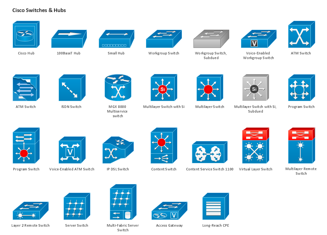
Design Element: Cisco for Network Diagrams

Building Drawing. Design Element: Piping Plan


IDEF0 standard with ConceptDraw DIAGRAM

 Wireless Networks
The Wireless Networks Solution extends ConceptDraw DIAGRAM software with professional diagramming tools, set of wireless network diagram templates and samples, comprehensive library of wireless communications and WLAN objects to help network engineers and designers efficiently design and create Wireless network diagrams that illustrate wireless networks of any speed and complexity, and help to identify all required equipment for construction and updating wireless networks, and calculating their costs.
- School Management System Erd Diagram
- School Management System ER Diagram
- Er Model For School Management System
- Dfd For Library Management System Student And Librarian
- Er Diagram Examples For School Management
- Data Flow Diagram On School Management System On Yourdon ...
- ERD Symbols and Meanings | Entity-Relationship Diagram ( ERD ...
- Use Case And Er Diagrams For Online Bank Management System
- Context Diagram For School Management System
- Data Flow Diagram Of The School Library Management System
- Er Diagram For Bank Management System Pdf
- Template For School Management System Class Diagram
- Entity-Relationship Diagram ( ERD ) | Football | School and Training ...
- Draw A Dfd Of Schools Libary
- Dfd Of School Library
- School Management System Analysis
- Sequence Diagram Example Of School Accounting System
- News System Er Schema
- Dfd Of School Labrary
- Entity-Relationship Diagram ( ERD ) | Windows Azure | Football ...