ERD Symbols and Meanings


Entity Relationship Diagram Symbols

 Entity-Relationship Diagram (ERD)
An Entity-Relationship Diagram (ERD) is a visual presentation of entities and relationships. That type of diagrams is often used in the semi-structured or unstructured data in databases and information systems. At first glance ERD is similar to a flowch
Entity Relationship Diagram Software Engineering

ConceptDraw DIAGRAM ER Diagram Tool

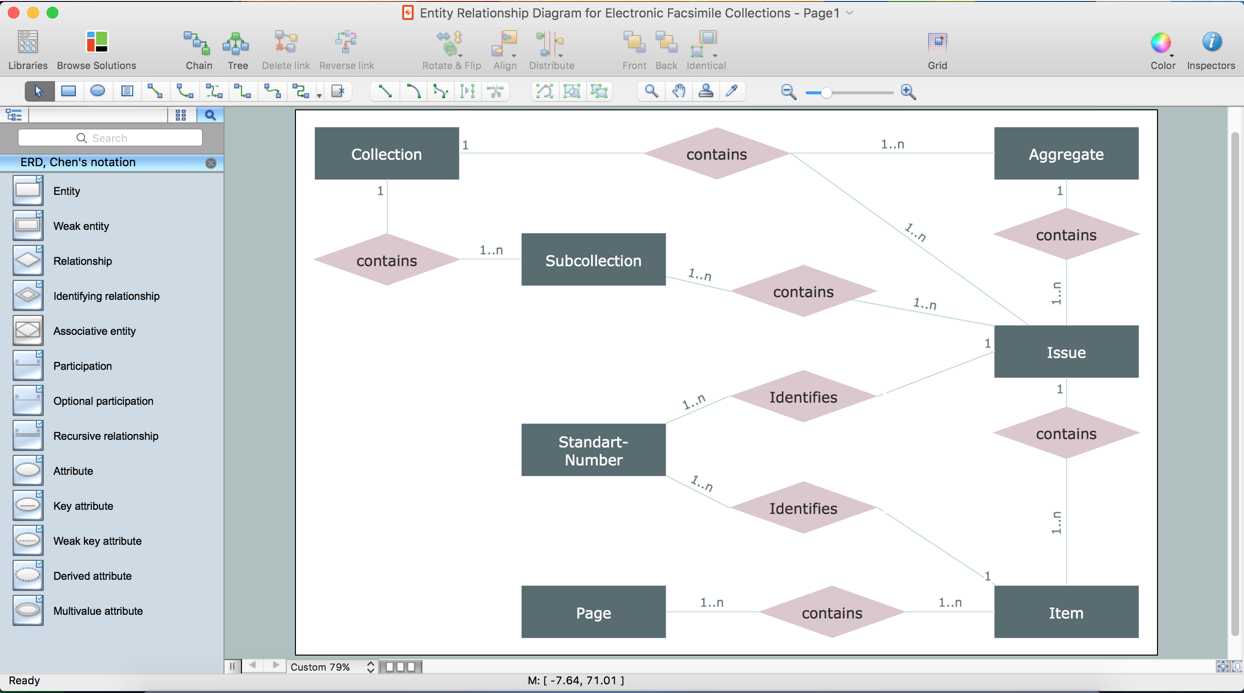
Drawing ER diagrams on a Mac
ER Diagram for Cloud Computing

Entity Relationship Diagram Examples

Entity Relationship Diagram - ERD - Software for Design Chen ER Diagrams
_Win_Mac.png)
Entity-Relationship Diagram

- Draw An Er Diagram Using Word
- How To Draw Entity Relationship Diagrams On Ms Word
- How To Draw Erd Diagram In Microsoft Word
- How To Draw Entity Relationship Diagram In Microsoft Word
- How To Make ER Diagram In Ms Word
- How To Make Entity Relationship Diagram On Ms Word
- Erd Diagram For Library Management For Word File
- How To Draw Erd Using Word
- Entity Relationship Diagram Word
- How To Make Chen ER Diagram | Drawing Er Diagrams In Word