UML Use Case Diagram Example. Registration System

Financial Trade UML Use Case Diagram Example

Entity Relationship Diagram Software Engineering

UML Class Diagram Generalization Example UML Diagrams

Data Flow Diagrams

ORM Diagram

Entity-Relationship Diagram

Data Flow Diagram Symbols. DFD Library

Property Management Examples

UML Tool & UML Diagram Examples

Interaction Overview Diagram


UML Tool & UML Diagram Examples
UML Class Diagram Example - Buildings and Rooms

 ATM UML Diagrams
The ATM UML Diagrams solution lets you create ATM solutions and UML examples. Use ConceptDraw DIAGRAM as a UML diagram creator to visualize a banking system.
The vector stencils library "UML use case diagrams" contains 25 symbols for the ConceptDraw PRO diagramming and vector drawing software.
"Use case diagrams are usually referred to as behavior diagrams used to describe a set of actions (use cases) that some system or systems (subject) should or can perform in collaboration with one or more external users of the system (actors). Each use case should provide some observable and valuable result to the actors or other stakeholders of the system. ...
Use case diagrams are in fact twofold - they are both behavior diagrams, because they describe behavior of the system, and they are also structure diagrams - as a special case of class diagrams where classifiers are restricted to be either actors or use cases related to each other with associations. ...
Use case is usually shown as an ellipse containing the name of the use case. ...
Name of the use case could also be placed below the ellipse. ...
If a subject (or system boundary) is displayed, the use case ellipse is visually located inside the system boundary rectangle. Note, that this does not necessarily mean that the subject classifier owns the contained use cases, but merely that the use case applies to that classifier. ...
A list of use case properties - operations and attributes - could be shown in a compartment within the use case oval below the use case name. ...
Use case with extension points may be listed in a compartment of the use case with the heading extension points. ...
A use case can also be shown using the standard rectangle notation for classifiers with an ellipse icon in the upper right-hand corner of the rectangle and with optional separate list compartments for its features. ...
Subject (sometimes called a system boundary) is presented by a rectangle with subject's name, associated keywords and stereotypes in the upper left corner. Use cases applicable to the subject are located inside the rectangle and actors - outside of the system boundary. ...
Standard UML notation for actor is "stick man" icon with the name of the actor above or below of the icon. Actor names should follow the capitalization and punctuation guidelines for classes. The names of abstract actors should be shown in italics. ...
Custom icons that convey the kind of actor may also be used to denote an actor, such as using a separate icon(s) for non-human actors. ...
An actor may also be shown as a class rectangle with the standard keyword «actor», having usual notation for class compartments ...
An actor can only have binary associations to use cases, components, and classes. ...
An association between an actor and a use case indicates that the actor and the use case somehow interact or communicate with each other.
Only binary associations are allowed between actors and use cases.
An actor could be associated to one or several use cases. ...
A use case may have one or several associated actors." [uml-diagrams.org/ use-case-diagrams.html]
The example "Design elements - UML use case diagrams" is included in the Rapid UML solution from the Software Development area of ConceptDraw Solution Park.
UML use case diagram symbols

"Banks offer many different channels to access their banking and other services:
(1) Automated Teller Machines.
(2) A branch is a retail location.
(3) Call center.
(4) Mail: most banks accept cheque deposits via mail and use mail to communicate to their customers, e.g. by sending out statements.
(5) Mobile banking is a method of using one's mobile phone to conduct banking transactions.
(6) Online banking is a term used for performing multiple transactions, payments etc. over the Internet.
(7) Relationship Managers, mostly for private banking or business banking, often visiting customers at their homes or businesses.
(8) Telephone banking is a service which allows its customers to conduct transactions over the telephone with automated attendant or when requested with telephone operator.
(9) Video banking is a term used for performing banking transactions or professional banking consultations via a remote video and audio connection. Video banking can be performed via purpose built banking transaction machines (similar to an Automated teller machine), or via a video conference enabled bank branch clarification.
(10) DSA is a Direct Selling Agent, who works for the bank based on a contract. Its main job is to increase the customer base for the bank." [Bank. Wikipedia]
The UML use case diagram example "Banking system" was created using the ConceptDraw PRO diagramming and vector drawing software extended with the Rapid UML solution from the Software Development area of ConceptDraw Solution Park.
UML use case diagram

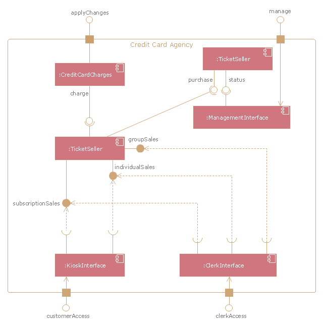
"A credit card is a payment card issued to users as a system of payment. It allows the cardholder to pay for goods and services based on the holder's promise to pay for them. The issuer of the card creates a revolving account and grants a line of credit to the consumer (or the user) from which the user can borrow money for payment to a merchant or as a cash advance to the user." [Credit card. Wikipedia]
The UML component diagram example "Credit card agency" was created using the ConceptDraw PRO diagramming and vector drawing software extended with the Rapid UML solution from the Software Development area of ConceptDraw Solution Park.
The UML component diagram example "Credit card agency" was created using the ConceptDraw PRO diagramming and vector drawing software extended with the Rapid UML solution from the Software Development area of ConceptDraw Solution Park.
UML component diagram
The vector stencils library "Sales workflow" contains 39 sales workflow symbols.
Use these sales icon set to draw your sales flowcharts, workflow diagrams and process charts with the ConceptDraw PRO diagramming and vector drawing software.
The sales pictograms library "Sales workflow" is included in the Sales Flowcharts solution from the Marketing area of ConceptDraw Solution Park.
Accounting software

Accounts

Activities

ATM

Call-taker, man

Call-taker, woman

Cash register

Contacts

Credit card transactions

Dealer

Direct mail

Dispatcher, man

Dispatcher, woman

Distribution point

Electronic mall

Invoice

Landing page

Lead

Lead conversion

Leads

New products

Nurturing

Online bank

Online order

Online payment

Products on sale

Product database

Product

Opportunities

Prospects

Proforma invoice

Sales

Sales funnel

Sales manager, man

Sales manager, woman

Sales orders

Sales representative

Shipping provider

Social profile

- Online Course Registration System Er Diagram
- ATM UML Diagrams | Er Diagram Student Course Registration System
- ATM UML Diagrams | Online Student Registration System Erd
- UML Use Case Diagram Example. Registration System | Entity ...
- Entity Relationship Diagram - ERD - Software for Design Crows Foot ...
- Uml Diagrams For Online Course Registration System
- Class Diagram Of Student Course Registration System
- UML Use Case Diagram Example. Registration System | UML ...
- Draw An Er Diagram For Student Enrollment System
- Entity Relationship Diagram - ERD
- UML Use Case Diagram Example. Registration System | UML Class ...
- UML Use Case Diagram Example. Registration System | Interaction ...
- UML Use Case Diagram Example. Registration System | UML ...
- E-R Diagrams | Data Modeling with Entity Relationship Diagram ...
- Block Diagram Of Online Course Management System
- UML Use Case Diagrams | UML Sample Project | UML 2 4 Process ...
- Data Flow Diagram Examples | Data Modeling with Entity ...
- Entity-Relationship Diagram ( ERD ) | | Exam Registration Er Diagram
- UML Use Case Diagram Example Registration System | Data Flow ...
- UML Use Case Diagram Example Registration System | UML ...