Mechanical Drawing Symbols

Process Flow Diagram Symbols
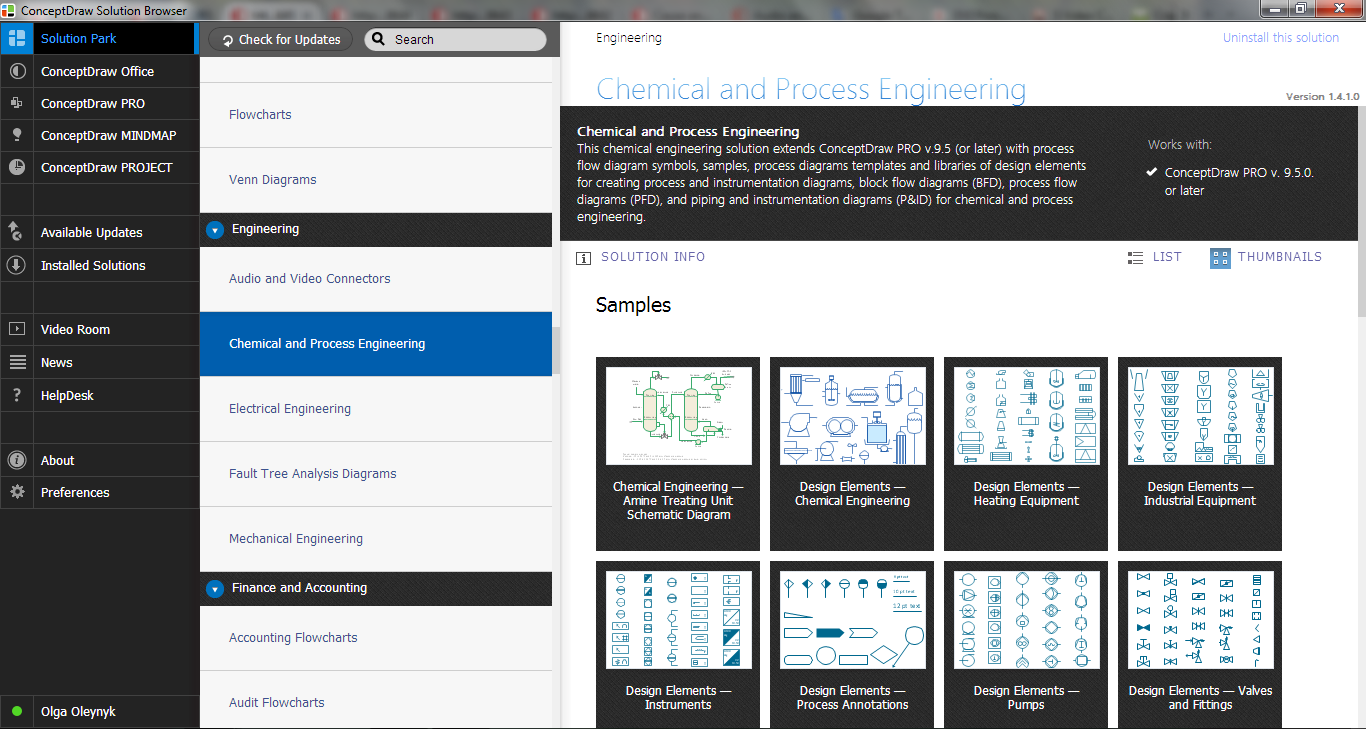
 Mechanical Engineering
This solution extends ConceptDraw DIAGRAM.9 mechanical drawing software (or later) with samples of mechanical drawing symbols, templates and libraries of design elements, for help when drafting mechanical engineering drawings, or parts, assembly, pneumatic,
Electrical Symbols, Electrical Diagram Symbols

Electrical Symbols — Transformers and Windings
Electrical Drawing Software and Electrical Symbols

Electrical Symbols — Lamps, Acoustics, Readouts

Technical Drawing Software

Electrical Symbols — Logic Gate Diagram

Electrical Symbols — Transistors
- Symbol Of Engenering Drawing
- Mechanical Drawing Symbols | Mechanical Engineering ...
- Important Symbols Of Engineering Drawing
- Mechanical Bearing Symbol On Engineering Drawing
- Mechanical Drawing Symbols | Process Flow Diagram Symbols ...
- Process Flow Diagram Symbols | Mechanical Drawing Symbols ...
- Mechanical Engineering | Mechanical Drawing Symbols | How To ...
- Symbol Of Fan In Engineering Drawing
- Process Flowchart | Mechanical Drawing Symbols | Mechanical ...
- Mechanical Drawing Symbols | Mechanical Engineering | How to ...