The vector stencils library "Switches" contains 25 symbols of electrical and light switches and breakers.
"In electrical engineering, a switch is an electrical component that can break an electrical circuit, interrupting the current or diverting it from one conductor to another.
The most familiar form of switch is a manually operated electromechanical device with one or more sets of electrical contacts, which are connected to external circuits.
A switch may be directly manipulated by a human as a control signal to a system, ... or to control power flow in a circuit, such as a light switch. Automatically operated switches can be used to control the motions of machines, for example, to indicate that a garage door has reached its full open position or that a machine tool is in a position to accept another workpiece. Switches may be operated by process variables such as pressure, temperature, flow, current, voltage, and force, acting as sensors in a process and used to automatically control a system. For example, a thermostat is a temperature-operated switch used to control a heating process. A switch that is operated by another electrical circuit is called a relay." [Switch. Wikipedia]
Use the design elements library "Switches" for drawing light switches layouts, electrical and telecommunication equipment floor plans for building design and construction using the ConceptDraw PRO diagramming and vector drawing software.
The shapes library "Switches" is included in the Electric and Telecom Plans solution from the Building Plans area of ConceptDraw Solution Park.
Electrical switch symbols

The vector stencils library "Switches and relays" contains 58 symbols of electrical contacts, switches, relays, circuit breakers, selectors, connectors, disconnect devices, switching circuits, current regulators, and thermostats for electrical devices.
"In electrical engineering, a switch is an electrical component that can break an electrical circuit, interrupting the current or diverting it from one conductor to another.
The most familiar form of switch is a manually operated electromechanical device with one or more sets of electrical contacts, which are connected to external circuits. Each set of contacts can be in one of two states: either "closed" meaning the contacts are touching and electricity can flow between them, or "open", meaning the contacts are separated and the switch is nonconducting. The mechanism actuating the transition between these two states (open or closed) can be either a "toggle" (flip switch for continuous "on" or "off") or "momentary" (push-for "on" or push-for "off") type.
A switch may be directly manipulated by a human as a control signal to a system, such as a computer keyboard button, or to control power flow in a circuit, such as a light switch. Automatically operated switches can be used to control the motions of machines, for example, to indicate that a garage door has reached its full open position or that a machine tool is in a position to accept another workpiece. Switches may be operated by process variables such as pressure, temperature, flow, current, voltage, and force, acting as sensors in a process and used to automatically control a system. ... A switch that is operated by another electrical circuit is called a relay. Large switches may be remotely operated by a motor drive mechanism. Some switches are used to isolate electric power from a system, providing a visible point of isolation that can be padlocked if necessary to prevent accidental operation of a machine during maintenance, or to prevent electric shock." [Switch. Wikipedia]
"A relay is an electrically operated switch. Many relays use an electromagnet to mechanically operate a switch, but other operating principles are also used, such as solid-state relays. Relays are used where it is necessary to control a circuit by a low-power signal (with complete electrical isolation between control and controlled circuits), or where several circuits must be controlled by one signal. The first relays were used in long distance telegraph circuits as amplifiers: they repeated the signal coming in from one circuit and re-transmitted it on another circuit. Relays were used extensively in telephone exchanges and early computers to perform logical operations.
A type of relay that can handle the high power required to directly control an electric motor or other loads is called a contactor. Solid-state relays control power circuits with no moving parts, instead using a semiconductor device to perform switching. Relays with calibrated operating characteristics and sometimes multiple operating coils are used to protect electrical circuits from overload or faults; in modern electric power systems these functions are performed by digital instruments still called "protective relays"." [Relay. Wikipedia]
The shapes example "Design elements - Switches and relays" was drawn using the ConceptDraw PRO diagramming and vector drawing software extended with the Electrical Engineering solution from the Engineering area of ConceptDraw Solution Park.
Switch and relay symbols

The vector stencils library "Analog and digital logic" contains 40 element symbols of logic (threshold) gates, bistable current switches, current controllers, regulators, electrical generators, and amplifiers.
Use it for drawing the digital and analog functions in electronic circuit diagrams and electrical schematics.
"Analogue electronics (or analog in American English) are electronic systems with a continuously variable signal, in contrast to digital electronics where signals usually take only two different levels. The term "analogue" describes the proportional relationship between a signal and a voltage or current that represents the signal." [Analogue electronics. Wikipedia]
"Digital electronics, or digital (electronic) circuits, represent signals by discrete bands of analog levels, rather than by a continuous range. All levels within a band represent the same signal state. Relatively small changes to the analog signal levels due to manufacturing tolerance, signal attenuation or parasitic noise do not leave the discrete envelope, and as a result are ignored by signal state sensing circuitry.
In most cases the number of these states is two, and they are represented by two voltage bands: one near a reference value (typically termed as "ground" or zero volts) and a value near the supply voltage, corresponding to the "false" ("0") and "true" ("1") values of the Boolean domain respectively.
Digital techniques are useful because it is easier to get an electronic device to switch into one of a number of known states than to accurately reproduce a continuous range of values.
Digital electronic circuits are usually made from large assemblies of logic gates, simple electronic representations of Boolean logic functions." [Digital electronics. Wikipedia]
The example "Design elements - Analog and digital logic" was drawn using the ConceptDraw PRO diagramming and vector drawing software extended with the Electrical Engineering solution from the Engineering area of ConceptDraw Solution Park.
Analog and digital logic elements

The vector stencils library "Semiconductors" contains 22 symbols of rectifiers, diodes, charge transfer and electronic conduction devices, switches, cathodes, transistors, thyristors, and transceivers for semiconductor (SIS) design.
"Semiconductor devices are electronic components that exploit the electronic properties of semiconductor materials, principally silicon, germanium, and gallium arsenide, as well as organic semiconductors. Semiconductor devices have replaced thermionic devices (vacuum tubes) in most applications. They use electronic conduction in the solid state as opposed to the gaseous state or thermionic emission in a high vacuum.
Semiconductor devices are manufactured both as single discrete devices and as integrated circuits (ICs), which consist of a number - from a few (as low as two) to billions - of devices manufactured and interconnected on a single semiconductor substrate, or wafer. ...
All transistor types can be used as the building blocks of logic gates, which are fundamental in the design of digital circuits. In digital circuits like microprocessors, transistors act as on-off switches; in the MOSFET, for instance, the voltage applied to the gate determines whether the switch is on or off.
Transistors used for analog circuits do not act as on-off switches; rather, they respond to a continuous range of inputs with a continuous range of outputs. Common analog circuits include amplifiers and oscillators.
Circuits that interface or translate between digital circuits and analog circuits are known as mixed-signal circuits.
Power semiconductor devices are discrete devices or integrated circuits intended for high current or high voltage applications. Power integrated circuits combine IC technology with power semiconductor technology, these are sometimes referred to as "smart" power devices. Several companies specialize in manufacturing power semiconductors." [Semiconductor device. Wikipedia]
The shapes example "Design elements - Semiconductors" was drawn using the ConceptDraw PRO diagramming and vector drawing software extended with the Electrical Engineering solution from the Engineering area of ConceptDraw Solution Park.
Semiconductor elements

 Cisco Network Diagrams
Cisco Network Diagrams solution extends ConceptDraw PRO software with samples, templates and libraries of vector stencils for drawing the Cisco computer network diagrams.
The vector stencils library "Transistors" contains 30 symbols of transistors drawing electronic schematics and circuit diagrams.
"A transistor is a semiconductor device used to amplify and switch electronic signals and electrical power. It is composed of semiconductor material with at least three terminals for connection to an external circuit. A voltage or current applied to one pair of the transistor's terminals changes the current through another pair of terminals. Because the controlled (output) power can be higher than the controlling (input) power, a transistor can amplify a signal. Today, some transistors are packaged individually, but many more are found embedded in integrated circuits.
The transistor is the fundamental building block of modern electronic devices, and is ubiquitous in modern electronic systems. ...
Transistors are categorized by:
(1) Semiconductor material...: the metalloids germanium ... and silicon ... in amorphous, polycrystalline and monocrystalline form; the compounds gallium arsenide ... and silicon carbide ..., the alloy silicon-germanium ..., the allotrope of carbon graphene ...
(2) Structure: BJT, JFET, IGFET (MOSFET), insulated-gate bipolar transistor, "other types"
(3) Electrical polarity (positive and negative): n–p–n, p–n–p (BJTs); n-channel, p-channel (FETs)
(4) Maximum power rating: low, medium, high
(5) Maximum operating frequency: low, medium, high, radio (RF), microwave frequency...
(6) Application: switch, general purpose, audio, high voltage, super-beta, matched pair
(7) Physical packaging: through-hole metal, through-hole plastic, surface mount, ball grid array, power modules...
(8) Amplification factor..." [Transistor. Wikipedia]
The shapes example "Design elements - Transistors" was drawn using the ConceptDraw PRO diagramming and vector drawing software extended with the Electrical Engineering solution from the Engineering area of ConceptDraw Solution Park.
Transistor symbols

 Electric and Telecom Plans
This solution extends ConceptDraw PRO software with samples, templates and libraries of vector stencils for drawing the Electric and Telecom Plans.
The vector stencils library "Electrical circuits" contains 49 element symbols of electrical and electronic devices, including ignitors, starters, transmitters, circuit protectors, transducers, radio and audio equipment.
Use it for drawing electronic circuit diagrams and electrical schematics.
"An electrical network is an interconnection of electrical elements such as resistors, inductors, capacitors, voltage sources, current sources and switches. An electrical circuit is a network consisting of a closed loop, giving a return path for the current. Linear electrical networks, a special type consisting only of sources (voltage or current), linear lumped elements (resistors, capacitors, inductors), and linear distributed elements (transmission lines), have the property that signals are linearly superimposable. They are thus more easily analyzed, using powerful frequency domain methods such as Laplace transforms, to determine DC response, AC response, and transient response.
A resistive circuit is a circuit containing only resistors and ideal current and voltage sources. Analysis of resistive circuits is less complicated than analysis of circuits containing capacitors and inductors. If the sources are constant (DC) sources, the result is a DC circuit.
A network that contains active electronic components is known as an electronic circuit. Such networks are generally nonlinear and require more complex design and analysis tools." [Electrical network. Wikipedia]
The symbils example "Design elements - Electrical circuits" was drawn using the ConceptDraw PRO diagramming and vector drawing software extended with the Electrical Engineering solution from the Engineering area of ConceptDraw Solution Park.
Electrical circuit elements

The vector stencils library Alarm and access control contains 80 symbols of digital proximity equipment, locking hardware, and access control equipment.
"An alarm device or system of alarm devices gives an audible, visual or other form of alarm signal about a problem or condition. Alarm devices are often outfitted with a siren." [Alarm device. Wikipedia]
"An access control point, which can be a door, turnstile, parking gate, elevator, or other physical barrier, where granting access can be electronically controlled. Typically, the access point is a door. An electronic access control door can contain several elements. At its most basic, there is a stand-alone electric lock. The lock is unlocked by an operator with a switch. To automate this, operator intervention is replaced by a reader. The reader could be a keypad where a code is entered, it could be a card reader, or it could be a biometric reader. Readers do not usually make an access decision, but send a card number to an access control panel that verifies the number against an access list. To monitor the door position a magnetic door switch can be used. In concept, the door switch is not unlike those on refrigerators or car doors. Generally only entry is controlled, and exit is uncontrolled. In cases where exit is also controlled, a second reader is used on the opposite side of the door. In cases where exit is not controlled, free exit, a device called a request-to-exit (REX) is used. Request-to-exit devices can be a push-button or a motion detector. When the button is pushed, or the motion detector detects motion at the door, the door alarm is temporarily ignored while the door is opened. Exiting a door without having to electrically unlock the door is called mechanical free egress. This is an important safety feature. In cases where the lock must be electrically unlocked on exit, the request-to-exit device also unlocks the door." [Access control. Wikipedia]
Use the design elements library Alarm and access control for drawing layout floor plans, blueprints, and wiring diagrams of intrusion systems, time and attendance systems, card and code access control security systems, internal and external security control systems using the ConceptDraw PRO diagramming and vector drawing software.
The shapes library Alarm and access control is included in the Security and Access Plans solution from the Building Plans area of ConceptDraw Solution Park.
Alarm and access control symbols

The vector stencils library "IGFET" contains 18 symbols of IGFET (insulated-gate field-effect transistor) elements for drawing electronic circuit diagrams.
"The metal–oxide–semiconductor field-effect transistor (MOSFET, MOS-FET, or MOS FET) is a transistor used for amplifying or switching electronic signals. Although the MOSFET is a four-terminal device with source (S), gate (G), drain (D), and body (B) terminals, the body (or substrate) of the MOSFET often is connected to the source terminal, making it a three-terminal device like other field-effect transistors. Because these two terminals are normally connected to each other (short-circuited) internally, only three terminals appear in electrical diagrams. The MOSFET is by far the most common transistor in both digital and analog circuits, though the bipolar junction transistor was at one time much more common. ...
An insulated-gate field-effect transistor or IGFET is a related term almost synonymous with MOSFET. The term may be more inclusive, since many "MOSFETs" use a gate that is not metal, and a gate insulator that is not oxide. Another synonym is MISFET for metal–insulator–semiconductor FET." [MOSFET
From Wikipedia]
The symbols example "Design elements - IGFET" was drawn using the ConceptDraw PRO diagramming and vector drawing software extended with the Electrical Engineering solution from the Engineering area of ConceptDraw Solution Park.
IGFET elements

"A logic gate is an idealized or physical device implementing a Boolean function, that is, it performs a logical operation on one or more logical inputs, and produces a single logical output. Depending on the context, the term may refer to an ideal logic gate, one that has for instance zero rise time and unlimited fan-out, or it may refer to a non-ideal physical device...
Logic gates are primarily implemented using diodes or transistors acting as electronic switches, but can also be constructed using electromagnetic relays (relay logic), fluidic logic, pneumatic logic, optics, molecules, or even mechanical elements. With amplification, logic gates can be cascaded in the same way that Boolean functions can be composed, allowing the construction of a physical model of all of Boolean logic, and therefore, all of the algorithms and mathematics that can be described with Boolean logic.
Logic circuits include such devices as multiplexers, registers, arithmetic logic units (ALUs), and computer memory, all the way up through complete microprocessors, which may contain more than 100 million gates. In practice, the gates are made from field-effect transistors (FETs), particularly MOSFETs (metal–oxide–semiconductor field-effect transistors).
Compound logic gates AND-OR-Invert (AOI) and OR-AND-Invert (OAI) are often employed in circuit design because their construction using MOSFETs is simpler and more efficient than the sum of the individual gates.
In reversible logic, Toffoli gates are used." [Logic gate. Wikipedia]
The logic gate diagram template for the ConceptDraw PRO diagramming and vector drawing software is included in the Electrical Engineering solution from the Engineering area of ConceptDraw Solution Park.
Logic gate diagram

This cafe electrical floor plan sample shows the outlet and switch layout.
"An electrical drawing, is a type of technical drawing that shows information about power, lighting, and communication for an engineering or architectural project. Any electrical working drawing consists of "lines, symbols, dimensions, and notations to accurately convey an engineering's design to the workers, who install the electrical system on the job".
A complete set of working drawings for the average electrical system in large projects usually consists of:
(1) A plot plan showing the building's location and outside electrical wiring.
(2) Floor plans showing the location of electrical systems on every floor.
(3) Power-riser diagrams showing panel boards.
(4) Control wiring diagrams.
(5) Schedules and other information in combination with construction drawings.
Electrical drafters prepare wiring and layout diagrams used by workers who erect, install, and repair electrical equipment and wiring in communication centers, power plants, electrical distribution systems, and buildings." [Electrical drawing. Wikipedia]
The outlet and switch layout example "Cafe electrical floor plan" was created using the ConceptDraw PRO diagramming and vector drawing software extended with the Electric and Telecom Plans solution from the Building Plans area of ConceptDraw Solution Park.
Outlet and switch layout

The vector stencils library "Switches" contains 25 symbols of electrical switches.
Use it for drawing electrical design floor and building plans, devices and equipment layouts in the ConceptDraw PRO diagramming and vector drawing software.
The vector stencils library "Switches" is included in the Electric and Telecom Plans solution from the Building Plans area of ConceptDraw Solution Park.
Single pole switch

Switch control

Dimmer switch

Dimmer switch 2

Double Pole Switch

Three-way switch

Four-way switch

Automatic door switch

Electrolier switch

Key operated switch

Switch and pilot lamp

Key operated switch with pilot light

Circuit breaker

Weatherproof circuit breaker

Momentary contact switch

Remote control switch

Weatherproof switch

Fused switch

Weatherproof fused switch

Switch with timer

Glow switch toggle

Horizontally mounted switch

Low voltage master switch

Low voltage switch

Single pole double throw switch

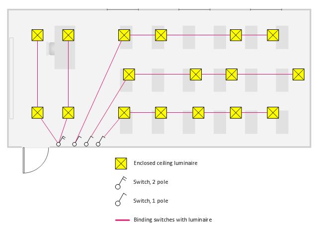
This electrical floor plan sample shows the lighting layout on the classroom reflected ceiling plan.
"Architectural lighting design is a field within architecture and architectural engineering that concerns itself primarily with the illumination of buildings. The objective of architectural lighting design is to obtain sufficient light for the purposes of the building, balancing factors of initial and operating cost, appearance, and energy efficiency. Lighting designers are often specialists who must understand the physics of light production and distribution, and the physiology and psychology of light perception by humans. Architectural lighting design is generally concerned with the permanent illumination of a structure. Concert and theatrical lighting have different purposes and practitioners." [Architectural lighting design. Wikipedia]
The electrical floor plan example "Classroom lighting - Reflected ceiling plan" was created using the ConceptDraw PRO diagramming and vector drawing software extended with the Electric and Telecom Plans solution from the Building plans area of ConceptDraw Solution Park.
Electrical floor plan
- Design elements - Analog and digital logic | Engineering | Simple ...
- Electrical Engineering | How to Create an Electrical Diagram | CAD ...
- Lighting and switch layout | Design elements - Electrical and telecom
- Bipolar current mirror - Circuit diagram | Hydraulic circuits | Circuit ...
- Cisco Switches and Hubs. Cisco icons, shapes, stencils and symbols
- Bipolar current mirror - Circuit diagram | Amplifier - Circuit diagram ...
- Technical Drawing Software | Electrical Drawing Software ...
- Design elements - Electrical circuits | Electrical Diagram Symbols ...
- Electrical Drawing Software | How To use House Electrical Plan ...
- Design elements - Electrical circuits | Electrical Engineering ...
- Cisco Switches and Hubs. Cisco icons, shapes, stencils and ...
- Basic Flowchart Symbols and Meaning | Process Flowchart | Design ...
- How to Create an Electrical Diagram | Mechanical Engineering ...
- Design elements - Analog and digital logic | External digital devices ...
- Design elements - Telecommunication networks ...
- Amplifier - Circuit diagram | Circuits and Logic Diagram Software ...
- Lighting and switch layout | Design elements - Switches | Switches ...
- Electric Switch Symbol
- Amplifier - Circuit diagram | Design elements - Transistors | Simple ...
- Design elements - Inductors | Design elements - Electrical circuits ...