Entity Relationship Diagram Software for Mac

Electrical Symbols — Maintenance

 Entity-Relationship Diagram (ERD)
An Entity-Relationship Diagram (ERD) is a visual presentation of entities and relationships. That type of diagrams is often used in the semi-structured or unstructured data in databases and information systems. At first glance ERD is similar to a flowch
Technical Drawing Software

Diagramming Software for Design UML Timing Diagrams


Electrical Symbols — Semiconductor

Electrical Symbols — Transformers and Windings
Entity Relationship Diagram Software Engineering

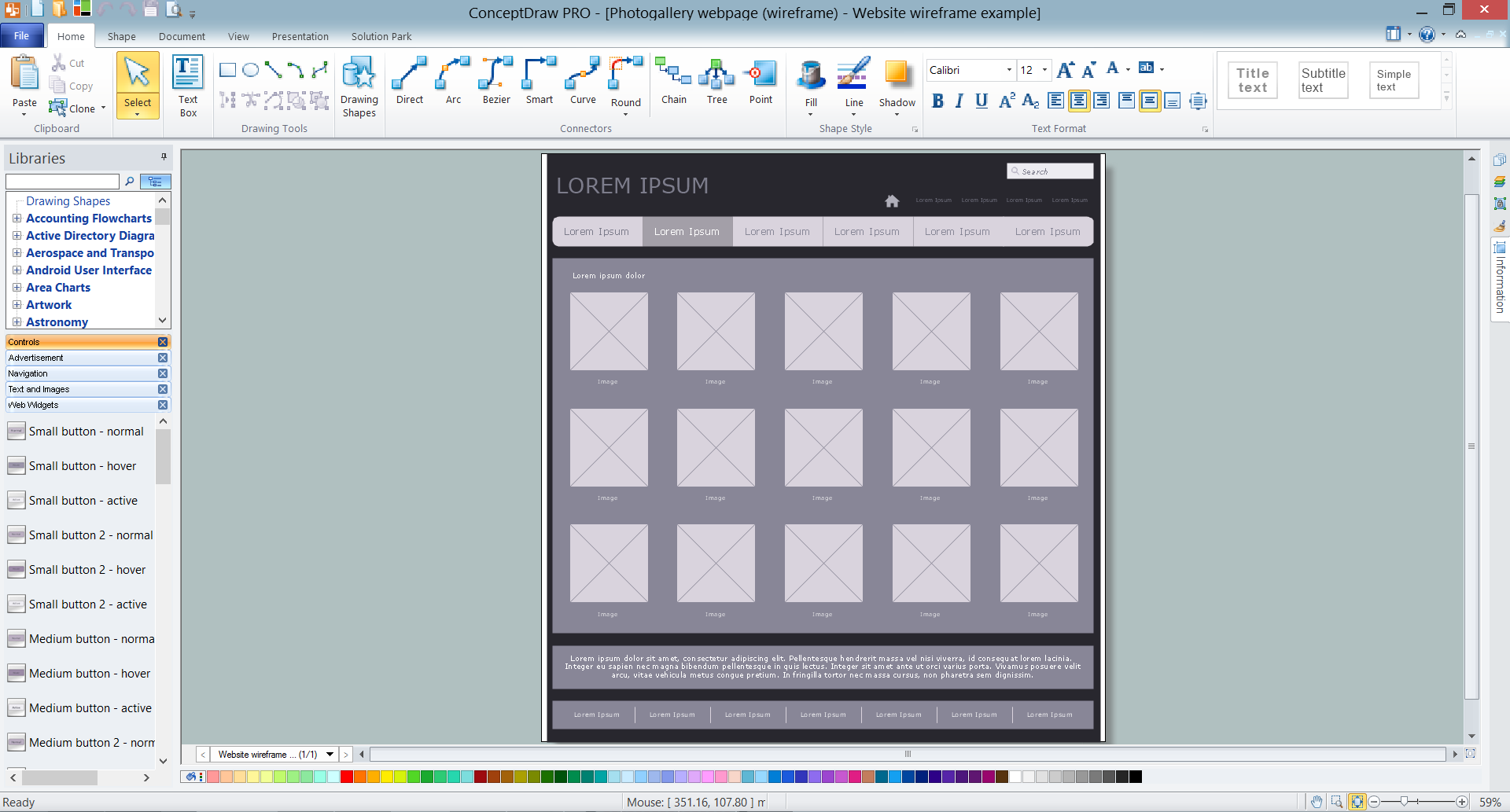
Wireframe Tools
ConceptDraw DIAGRAM ER Diagram Tool

- Er Diagram For Electricity Management System
- Er Diagram Of Electricity Bill Management System
- Process Flowchart | E R Diagram For Electricity Bill
- Electronic Shop Management System Project Erd
- Flow Chart Of Electricity Billing Management System
- Er Diagram For Solar System Management
- Online Electric Bill Payment Er Diagram
- Er Diagram Of Railway Management System
- Er Diagram For Electricity Billing System
- Example of DFD for Online Store (Data Flow Diagram) DFD ...